
Inverter control apparatus and control method thereof

a control apparatus and inverter technology, applied in the direction of motor/generator/converter stopper, dynamo-electric converter control, dc-ac conversion without reversal, etc., can solve the problem that the method of modulating a rotor-based q-axis current reference into a trapezoidal form cannot eliminate harmonic components of input current, and deteriorate system stability, so as to reduce the number of components and reduce the cost

Active Publication Date: 2014-01-30
SAMSUNG ELECTRONICS CO LTD +1
View PDF6 Cites 38 Cited by
  • Summary
  • Abstract
  • Description
  • Claims
  • Application Information

AI Technical Summary

Benefits of technology

The present invention provides a method for generating a rotor based q-axis current reference and a rotor based d-axis current reference to reduce pulsation of a DC link voltage. By using a small-capacitance capacitor for the DC link of an inverter, stable variable speed control of a motor can be achieved and the reliability of the inverter circuit can be improved. Additionally, the circuit for initially charging a capacitor can be eliminated using the small-capacitance capacitor, resulting in reduced costs and improved reliability of products.

Problems solved by technology

However, the method of modulating a rotor based q-axis current reference into a sine squared form does not consider a voltage drop due to inductance and stator resistance and needs an additional methodology for measuring the voltage of input power, such as a voltage sensor.
The method of modulating a rotor based q-axis current reference into a trapezoidal form cannot eliminate harmonic components of an input current.
Accordingly, instantaneous change of the d-axis current deteriorates system stability.

Method used


Image

  • Inverter control apparatus and control method thereof
  • Inverter control apparatus and control method thereof
  • Inverter control apparatus and control method thereof

Examples


Embodiment Construction

[0063]Reference will now be made in detail to the embodiments of the present invention, examples of which are illustrated in the accompanying drawings, wherein like reference numerals refer to like elements throughout.

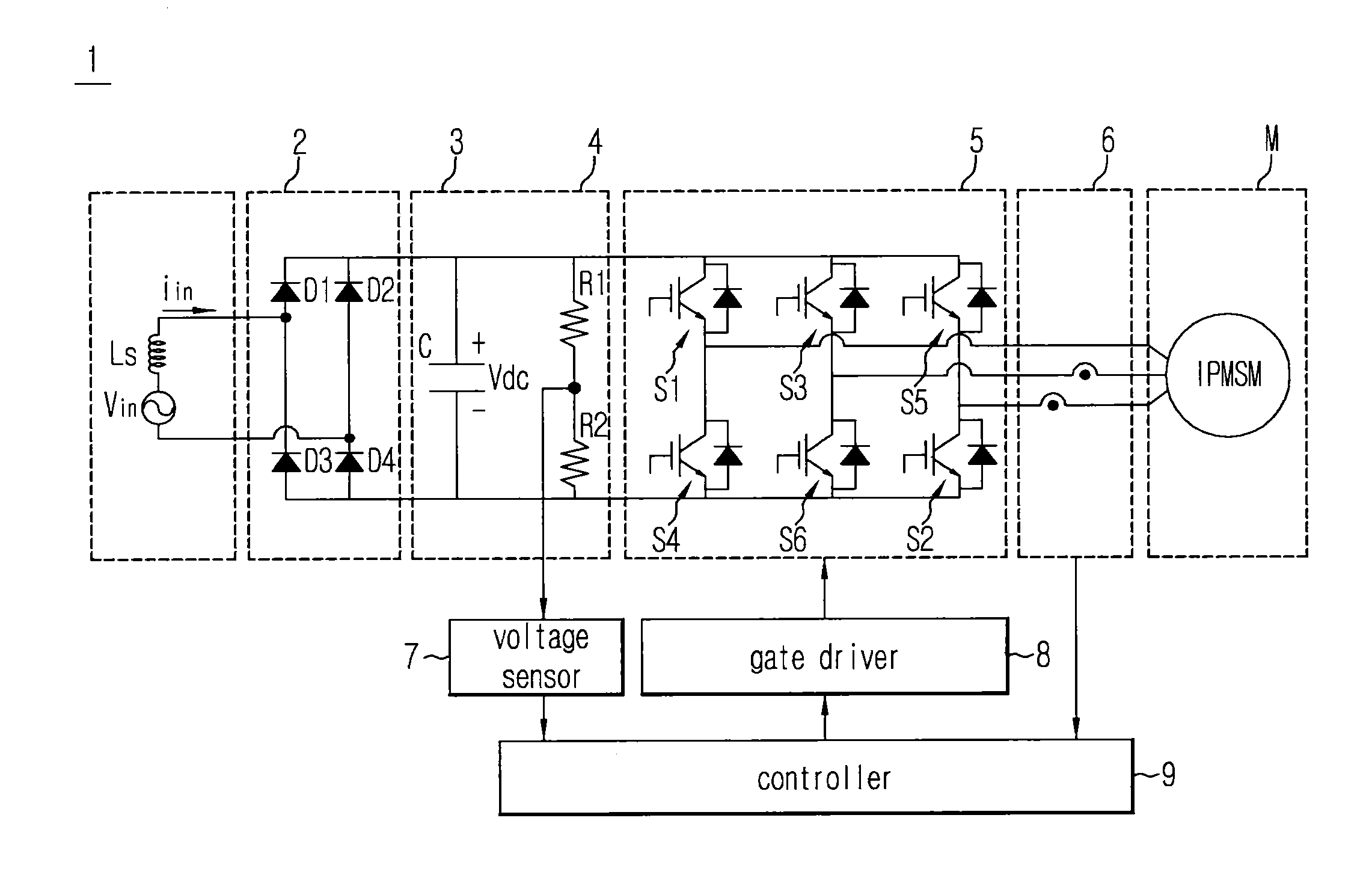
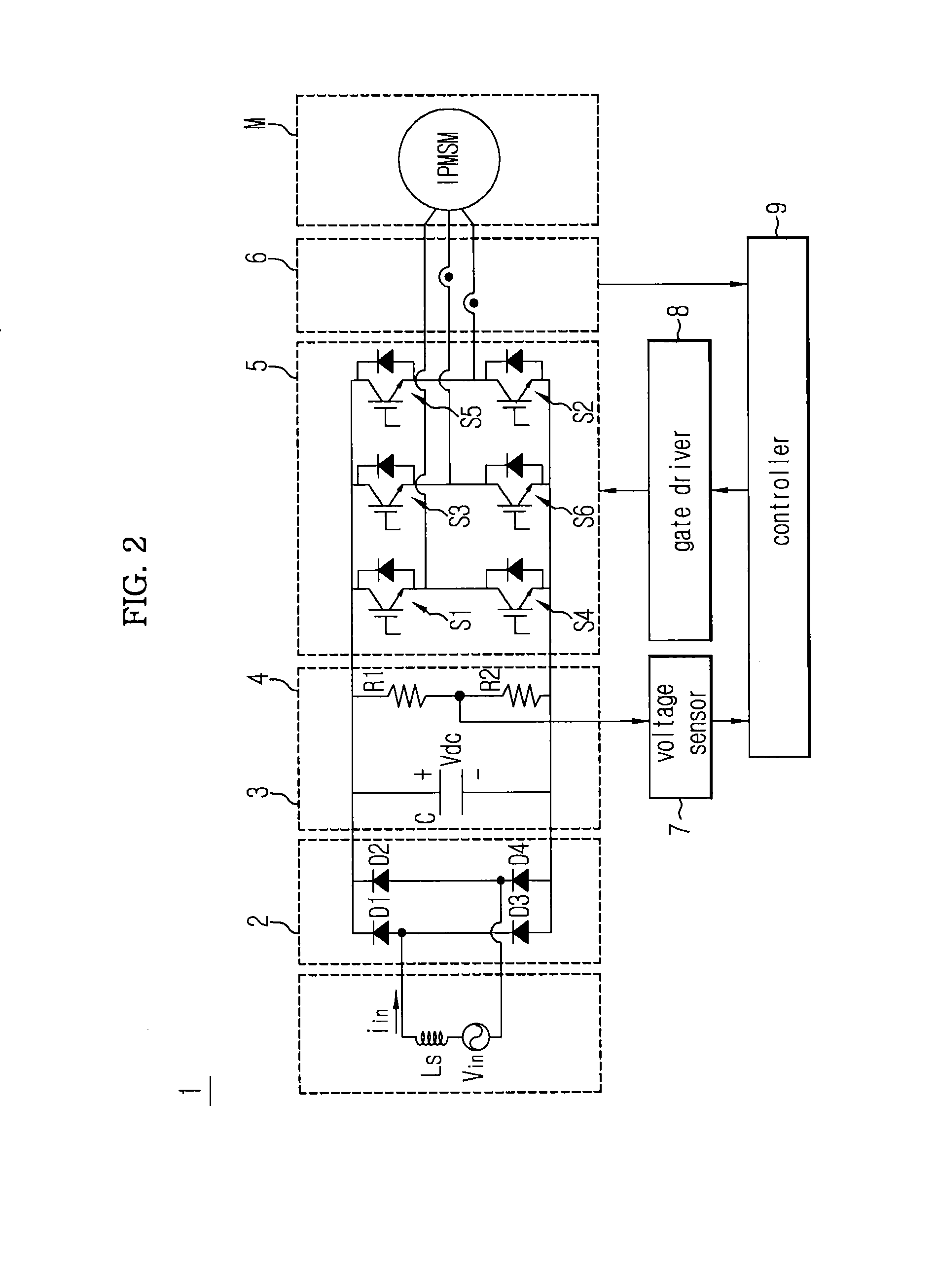
[0064]FIG. 2 illustrates an inverter control apparatus according to an embodiment of the present invention.

[0065]The inverter control apparatus 1 according to an embodiment of the present invention drives a three-phase motor and controls an inverter having a DC-link voltage that pulsates at a frequency twice a system frequency and includes a current sensor, a voltage sensor and a controller. The controller receives an inverter output current value from the current sensor and accepts an inverter DC-link voltage value from the voltage sensor to estimate a system angle or a system frequency. The controller generates a rotor based q-axis current reference in a sine squared form, which is synchronized with the system angle, averages a periodically varying voltage limit valu...


PUM


Abstract

An inverter control apparatus and a control method thereof are provided. The inverter control apparatus and a control method thereof stably operate a three-phase motor using a capacitor having a small capacitance for a DC link. The inverter control apparatus includes a current sensor to sense an output current of the inverter, a voltage sensor to sense a DC-link voltage of the inverter, and a controller to generate an average of a periodically varying rotor based q-axis current boundary value based on the output current and the DC-link voltage to generate a current reference on the basis of the average of the rotor based q-axis current boundary value, and to drive a three-phase motor based on the current reference. Stabilized variable speed control of a motor by using a small-capacitance capacitor for a DC link of an inverter is performed and reliability of an inverter circuit improved.

Description

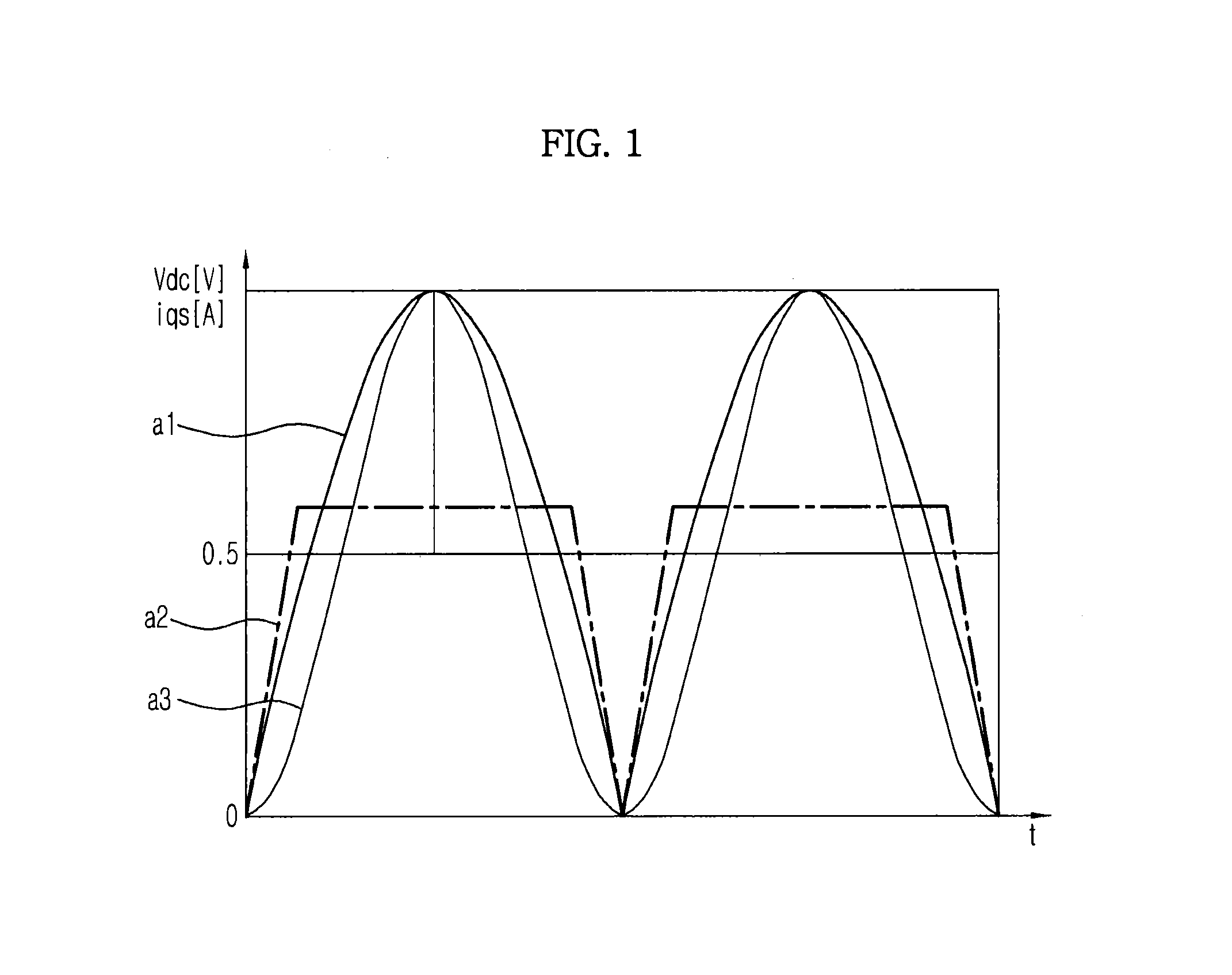
CROSS-REFERENCE TO RELATED APPLICATIONS[0001]This application is related to, and claims priority to, Korean Patent Application No. 2012-81486, filed on Jul. 25, 2012 in the Korean Intellectual Property Office, the disclosure of which is incorporated herein by reference.BACKGROUND[0002]1. Field[0003]Embodiments of the present invention relate to an inverter control apparatus and a control method thereof and, more particularly, to an inverter control apparatus and a control method thereof to stably operate a three-phase motor using a capacitor having a small capacitance for a DC link.[0004]2. Description of the Related Art[0005]FIG. 1 illustrates a waveform of a conventional q-axis current reference.[0006]Referring to FIG. 1, a DC-link voltage waveform a1, a q-axis current reference waveform a2 in a trapezoidal form, and a q-axis current reference waveform a3 in a sine squared form are illustrated.[0007]To stably operate a permanent magnet synchronous motor with an inverter using a sm...

Claims


Application Information

Patent Timeline
IPC IPC(8): H02P27/06
CPCH02P27/06H02P2207/05H02M1/4208H02P21/22H02P21/18H02P21/20H02P23/26Y02B70/10H02M7/48H02M1/14H02P6/183
Inventor PARK, YOUNG JAESEO, HAN SOLALEXEY, BODROVSUL, SEUNG KIJUNG, HYUN-SAMCHEE, SEUNG-JUN
Owner SAMSUNG ELECTRONICS CO LTD
Learn More