
Resin molding, method for manufacturing the same, and metal mold for manufacturing the same

Active Publication Date: 2014-01-30
SUZUKI MOTOR CO LTD
View PDF5 Cites 1 Cited by
  • Summary
  • Abstract
  • Description
  • Claims
  • Application Information

AI Technical Summary

Benefits of technology

This patent describes a method for manufacturing a metallic-toned resin molding that has high design properties and prevents appearance defects, even when multiple grooves are formed on its surface. By using a unique resin material and a specific design process, the molding achieves a high metallic feel with relatively high aspect ratio bright material and prevents the appearance of weld lines or flow marks. Additionally, the method utilizes a specific gate angle to further reduce appearance defects. This techniques can be applied to various garnishes and automotive parts, providing an improved design for high-end products.

Problems solved by technology

However, volatile organic compound (VOC) generated due to the painting causes an environmental load, and thus the discharge of the VOC has been regulated in recent years (for example, Air Pollution Control Act of Japan (amended in 2004)).
However, appearance defects such as a “weld line” or a “flow mark” are likely to occur when using such resin material to which the bright material is added.
In molding, a collision or a turbulent flow of the resin material occurs in the metal mold and thus flowability of the resin material deteriorates.
In particular, the appearance defects such as the weld line or the flow mark are likely to occur when rectangular grooves are formed on a design surface of an MT shift garnish.
Therefore, unlike the painting, it is very hard to maintain high design properties in the resin molding.
That is, it is very hard to secure the silver metallic tone which has high quality feeling while preventing the generation of the appearance defects.
Further, the appearance defects such as the weld line or the flow mark are also likely to occur when the resin material contains bright material having high aspect ratio since the flowability of the resin material is decreased due to the bright material.
This method disclosed in Patent Document 1 can suppress the weld line, but cannot completely eliminate the weld line.
Further, this method cannot be applied to bright material that has a maximum outer diameter smaller than 10 [μm].
However, this method disclosed in Patent Document 2 increases cost and causes difficulty in color matching.
Although Patent Document 2 mentions a high quality color tone such as a metallic tone or a pearl tone, can be obtained by the disclosed method, the metallic feeling significantly deteriorates when the weld-eliminating agent is added in actuality.
However, Patent Document 3 is completely silent about a molding formed with rectangular grooves on a design surface thereof.

Method used


Image

  • Resin molding, method for manufacturing the same, and metal mold for manufacturing the same
  • Resin molding, method for manufacturing the same, and metal mold for manufacturing the same
  • Resin molding, method for manufacturing the same, and metal mold for manufacturing the same

Examples


embodiment 1

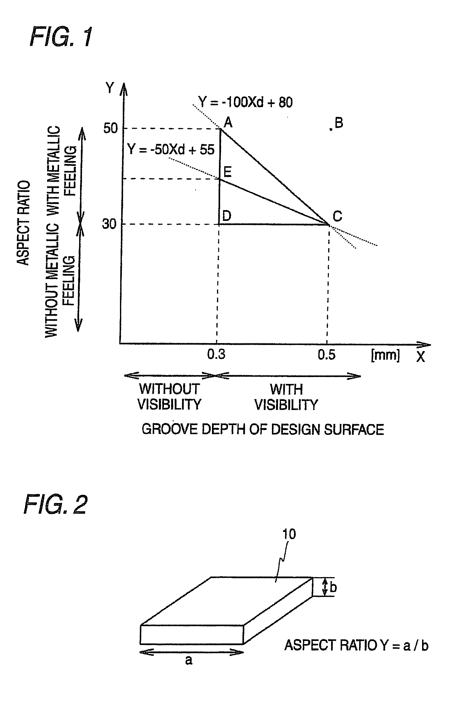
[0082]Embodiment 1 will be described below. In Embodiment 1, the above-mentioned Conditions 1 to 3 will be described in detail and Condition 4 is applied. First, the amount of the added bright material 10 (parts by weight) is examined. Then, a gate angle of Condition 4 will be described. Condition 4 corresponds to characteristics of Embodiment 2 (a manufacturing method) and Embodiment 3 (a metal mold).

[0083]

[0084]A test piece 28 shown in FIG. 6 was produced, a prototype of a resin molding that contained a bright material 10 having a relatively large aspect ratio Y was made, and a relationship between the amount of the added bright material 10 and strength of the test piece 28 was checked. Further, a hole 29 was formed at the test piece 28 so that the degree of generation of a weld line 30 could be evaluated. Furthermore, the flow mark 32 was likely to be generated near the gate 26. The AES resin was selected as a thermoplastic base resin, and a colorant was added.

[0085]The amount of...

embodiment 2

[0114]Embodiment 2 of this embodiment will be described below.

[0115]

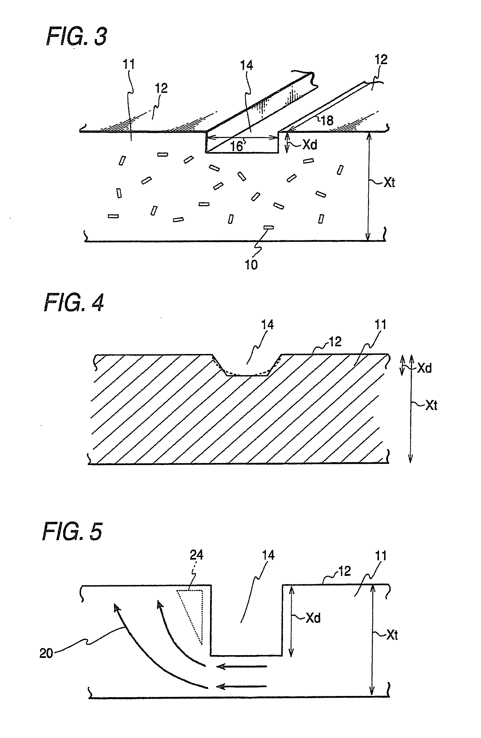
[0116]FIG. 13 is a partial view cross-sectional view showing an example of a plate 50 that is used in Embodiments 2 and 3. The plate 50 is superimposed on another plate (not shown), so that a cavity 52 having the shape corresponding to the design surface 12 shown in FIG. 10A is formed. A resin is supplied into the cavity 52 so as to fill the cavity and is hardened by cooling or the like, so that a product (a resin molding, for example, an MT shift garnish) is formed.

[0117]Further, a gate, which connects a plate 50 to a runner 54 of an injection molding machine, is disposed at an angle (45°) shown in FIG. 13 in order to make a resin supply angle (gate angle), which is formed with respect to the direction of the long side 18 of the groove 14, be in the ranges of θ1 and θ2 of Condition 4.

[0118]Referring to FIG. 14, in a manufacturing method of Embodiment 2, first, a cavity 52 corresponding to the shape of a molding 11 ...

embodiment 3

[0128]Embodiment 3 of this embodiment will be described below.

[0129]

[0130]FIG. 15 is a view showing an example of a metal mold, which forms two resin moldings, according to the invention, and is a plan view showing that resin moldings are placed on one plate 50. As shown in FIG. 15, a metal mold for a metallic tone resin molding of Embodiment 3 includes cavities 52 corresponding to the shape of a molding 11 that has rectangular grooves 14 on a design surface 12, gates 26 through which a resin containing a bright material 10 flows into the cavities 52, a sprue 56 that injects a resin to the gates through runners 54, and a plurality of plates 50 that forms the cavities 52.

[0131]Further, in Embodiment 3, according to Condition 4, the gate 26 is provided in the range of 45°±30° (θ1 shown in FIG. 9) when the direction of the long side of the groove 14 is regarded to correspond to 0°. Furthermore, when the aspect ratio Y or complexity of the design surface 12 is increased, the gate angle ...


PUM

PropertyMeasurementUnit
Percent by massaaaaaaaaaa
Angleaaaaaaaaaa

Abstract

A resin molding is provided. A main body is comprised of 100 parts by weight of thermoplastic resin and 0.1 to 4 parts by weight of bright material having the aspect ratio of 30 to 50. A main body has a design surface formed with a groove. The lower limit of the depth of the groove is set to 0.3 mm and the upper limit of the depth of the groove is set to 0.5 mm.

Description

CROSS-REFERENCE TO RELATED APPLICATIONS[0001]This application is a divisional of U.S. application Ser. No. 12 / 398,482, filed Mar. 5, 2009 in the U.S. Patent and Trademark Office, which claims the benefit of Japanese Patent Application No. 2008-070801, filed Mar. 19, 2008, in the Japanese Patent Office. All disclosures of the document(s) named above are incorporated herein by reference.BACKGROUND OF THE INVENTION[0002]1. Field of the Invention[0003]The present invention relates to a resin molding, a method for manufacturing the resin molding and a metal mold for manufacturing the resin molding by injection molding method, and more particularly, to a metallic tone resin molding that prevents generation of appearance defects and has a color with metallic feeling caused by bright material to have excellent design properties, and a method and a metal mold for manufacturing the metallic tone resin molding.[0004]2. Description of the Related Art[0005]A four-wheel vehicle provided with a ma...

Claims


Application Information

Patent Timeline
IPC IPC(8): B29C45/00
CPCB29C45/00B29C45/0013B29C45/0025B29C45/0046B29C45/2708B29L2031/30Y10T428/24479
Inventor NAGASHIMA, HIROAKIUEBAYASHI, HISASHIGE
Owner SUZUKI MOTOR CO LTD
Learn More