
Systems and methods for splitting droplets

a technology of system and droplet, applied in the field of fluidics and microfluidics, can solve the problems of difficult control of fluid flow in such systems, inconvenient production of large numbers of droplets, and insufficient use of techniques for large droplets

Inactive Publication Date: 2014-01-30
PRESIDENT & FELLOWS OF HARVARD COLLEGE
View PDF13 Cites 22 Cited by
  • Summary
  • Abstract
  • Description
  • Claims
  • Application Information

AI Technical Summary

Benefits of technology

The present invention relates to methods and devices for creating droplets in a microfluidic system. Specifically, the invention provides methods for splitting a parent droplet into multiple droplets, which can be useful in various applications such as inkjet printing, biological assays, and the production of uniform droplets. The methods involve creating a network of channels that receives droplets from an inlet channel, which can be designed to minimize the difference in velocity between the fastest and slowest droplets. The invention also includes devices that facilitate the creation and use of microfluidic droplets.

Problems solved by technology

However, such techniques have not been as useful for producing large numbers of droplets, e.g., from a single starting (or “parent”) droplet.
In addition, fluid flow rates through such systems are often not constant due to the increasing number of downstream channels, and thus, fluid flows in such systems are not easy to control.

Method used


Image

  • Systems and methods for splitting droplets
  • Systems and methods for splitting droplets
  • Systems and methods for splitting droplets

Examples


example 1

[0103]Double emulsions are droplets that contain additional smaller droplets inside. Because of their small dimensions and core-shell structure, they are useful for applications requiring microencapsulation, including foods, cosmetics, and pharmaceuticals. With microfluidic devices, double emulsion droplets can be formed with controlled properties, including controlled dimensions and volume fractions. The droplets can also be efficiently filled with active materials: typically, encapsulations of 100% efficiency can be achieved, whereas, by contrast, bulk methods achieve less than 10% of the actives encapsulated. Nevertheless, there are disadvantages to this approach; an important example results from the small dimensions of the devices, which leads to droplets being formed at very slow rates. Double emulsions are typically only formed only at milliliters per hour, which may be too slow for some applications.

[0104]One way to increase throughput is to parallelize the devices. Rather t...

example 2

[0110]Splitting can also be used to increase the rate of production of double emulsification droplets. In this example, a splitting array was added to the end of a large drop maker, e.g., as discussed in Example 1, though this time it was a double emulsion maker. The double emulsion device included two cross-channel junctions connected in series, as shown in FIG. 4B and the upper row of images in FIG. 5. The device was fabricated in poly(dimethylsiloxane) using the techniques of soft lithography, as discussed herein. The double emulsion device operated ˜5× faster than a conventional drop maker; the slower speed of the double emulsion device, relative to the device of Example 1, was due to the fewer number of splitting junctions.

[0111]FIG. 5 illustrates image sequences of double emulsions being formed using one-step double emulsification (top row) and being split into smaller droplets using splitting junctions (lower rows). The device bisected the double emulsions three times into da...

example 3

[0115]In this example, to quantify the dynamics of splitting, the lengths of the droplets along their central axes were measured as a function of time. See FIGS. 6A and 6B, respectively, showing the lengths (L / w) of single and double emulsion droplets as a function of time, measured from their back interfaces to the apex of the split in the splitting junction. The lengths were normalized by the width of the channel leading into the junction. For the double emulsions, the lengths of both the outer droplets (Lout) and inner droplets (Lin) are provided. The experiment was also performed at different Capillary numbers, as labeled.

[0116]In these experiments, the single emulsion droplets entered the splitting junction appeared to have a sausage shape, because they were initially confined in the narrow inlet channel. As they entered the splitting junction, two lobes developed on each of the droplets; the droplets initially did not entirely plug the channels, but allowed the surrounding con...


PUM


Abstract

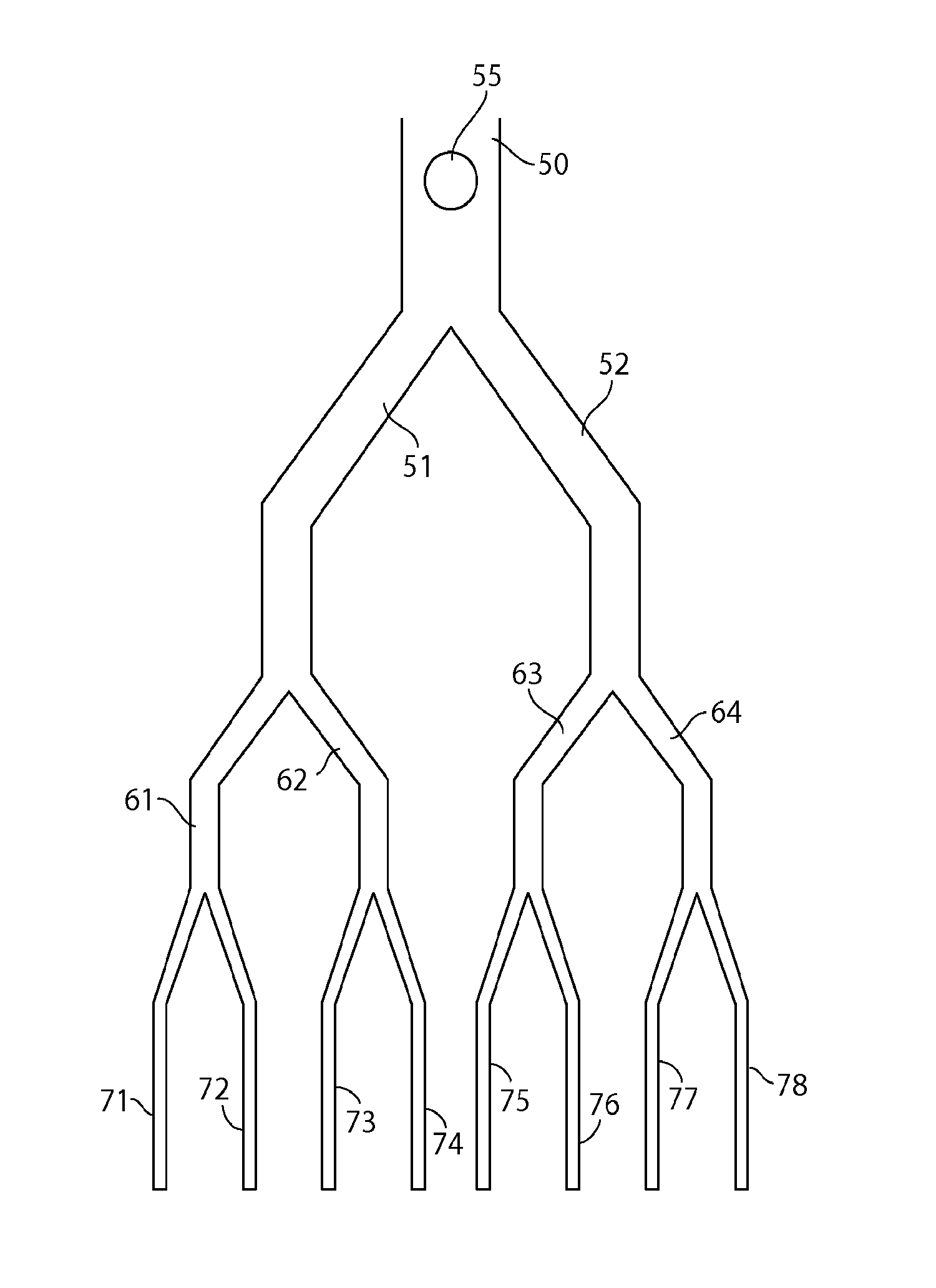
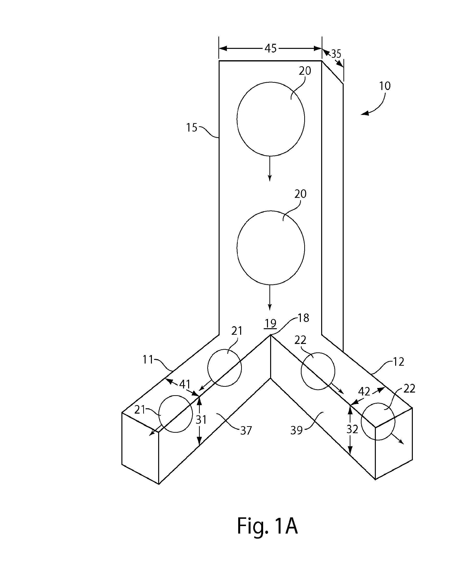
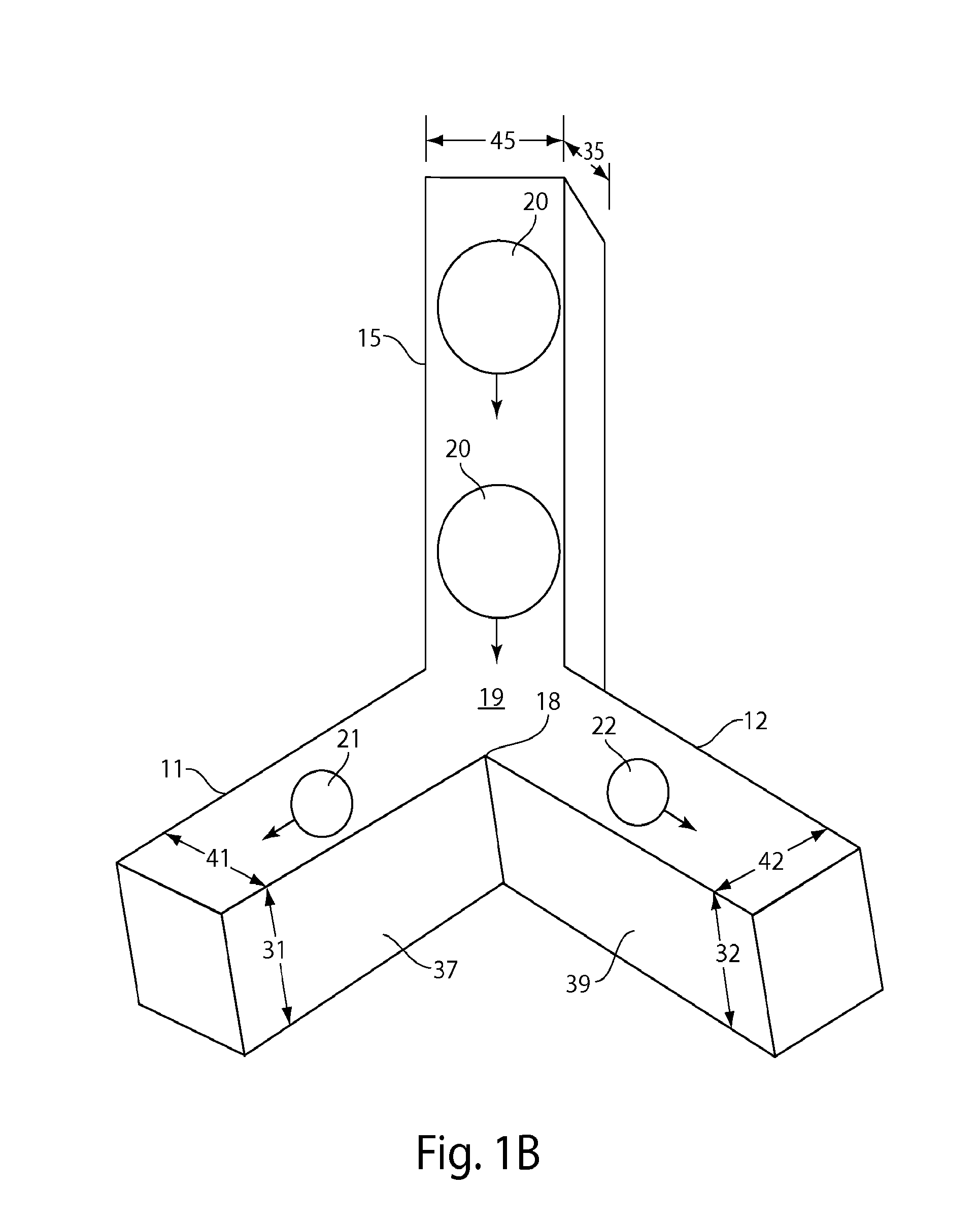
The present invention generally relates to fluidics and microfluidics and, in particular, to creating droplets in a fluidic system. In some aspects, the present invention is generally directed to systems and methods for splitting a parent droplet into two or more droplets, e.g., by urging the parent droplet towards an obstacle to split the parent droplet. In some cases, the parent droplet is split into at least first and second droplets which each are directed to separate channels. In some cases, the channels may be constructed and arranged such that the droplet velocities of the first and second droplets are substantially the same as the velocity of the parent droplet. In some cases, such droplets may be repeatedly split, e.g., a parent droplet is divided into 2 daughter droplets, then each droplet split again, etc., for example, such that one parent droplet may eventually be split into 22, 23, 24, 25, 26, etc. daughter droplets. In some cases, the daughter droplets may be substantially monodisperse.

Description

RELATED APPLICATIONS[0001]This application claims the benefit of U.S. Provisional Patent Application Ser. No. 61 / 440,198, filed Feb. 7, 2011, entitled “Systems and Methods for Splitting Droplets,” by Abate, et al., incorporated herein by reference.GOVERNMENT FUNDING[0002]Research leading to various aspects of the present invention were sponsored, at least in part, by NSF, Grant No. DMR-0602684, and MRSEC, Grant No. DMR-0820484. The U.S. Government has certain rights in the invention.FIELD OF INVENTION[0003]The present invention generally relates to fluidics and microfluidics and, in particular, to creating droplets in a fluidic system.BACKGROUND[0004]The manipulation of fluids to form fluid streams of desired configurations, discontinuous fluid streams, droplets, particles, dispersions, etc., for purposes of fluid delivery, product manufacture, analysis, and the like, is a relatively well-studied art. For example, highly monodisperse droplets, less than 100 micrometers in diameter, ...

Claims


Application Information

Patent Timeline
Patent Type & Authority Applications(United States)
IPC IPC(8): B01L3/00
CPCB01L3/5027B01L3/502784B01L2200/12B01L2300/0816B01L2300/0864B01L2200/0673B01L2300/123Y10T137/0318Y10T137/85938B01L3/00G01N33/48G01N35/08
Inventor ABATE, ADAM R.WEITZ, DAVID A.
Owner PRESIDENT & FELLOWS OF HARVARD COLLEGE
Learn More