Light-emitting apparatus capable of moving between retracted position and light-emitting position, image pickup apparatus having the light-emitting apparatus

a pickup apparatus and light-emitting technology, which is applied in the direction of lighting and heating apparatus, electric lighting emission/distribution, instruments, etc., can solve the problems of reducing the position accuracy of the electronic flash housing, generating vibration noise and reverberation noise, and reducing collision noise and vibration noise. , to achieve the effect of stably reducing vibration noise and so

Inactive Publication Date: 2014-01-23
CANON KK
View PDF0 Cites 3 Cited by
  • Summary
  • Abstract
  • Description
  • Claims
  • Application Information

AI Technical Summary

Benefits of technology

The present invention is a light-emitting apparatus that can be mounted in an image pickup apparatus. It was designed to reduce noise and vibration when the light-emitting apparatus is moved from a retracted position to a light-emitting position, even when the temperature changes. The light-emitting apparatus is insensitive to changes in environmental temperature, which means it is not affected by external factors like temperature changes. These factors can cause instability in the movement of the light-emitting apparatus, which can result in noise and vibration. The invention solves this issue by reducing the impact of external factors on the light-emitting apparatus, resulting in a more stable and reliable image pickup apparatus.

Problems solved by technology

In any of the arrangements described above, when the moving electronic flash is stopped by colliding it with a stopper portion provided in a camera body, a collision noise is generated and also, a vibration noise and a reverberation noise are generated in the whole of a camera, and these noises give a user a feeling of discomfort.
However, the above prior arts have problems that when the electronic flash is moved in the rotary mode, deformation of the stopper portion occurring as the number of use increases degrades the positional accuracy of a housing for the electronic flash.
When the positional accuracy of the housing for the electronic flash decreases, the angle of a direction in which light is emitted to a subject deviates, which may cause the contrast of a taken image to be uneven.
On the other hand, the stiffness of the elastic member is increased to some extent so as to improve the positional accuracy of the housing for the electronic flash, and it is thus thought that obtaining high silencing performance is difficult.
However, such a material becomes permanently distorted to a large degree particularly when left in a high-temperature environment, and a high degree of positional accuracy is difficult to obtain.

Method used


Image

  • Light-emitting apparatus capable of moving between retracted position and light-emitting position, image pickup apparatus having the light-emitting apparatus
  • Light-emitting apparatus capable of moving between retracted position and light-emitting position, image pickup apparatus having the light-emitting apparatus
  • Light-emitting apparatus capable of moving between retracted position and light-emitting position, image pickup apparatus having the light-emitting apparatus

Examples


first embodiment

[0023]A description will now be given of a digital camera which has a light-emitting apparatus of a type that is rectilinearly moved between a retracted position and a light-emitting position. Here, the digital camera is constructed such that the light-emitting apparatus formed as one unit is mounted in a camera body, and the light-emitting apparatus formed as one unit will hereafter be referred to as “the electronic flash unit”.

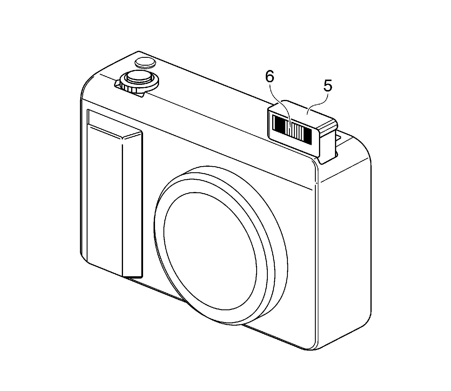
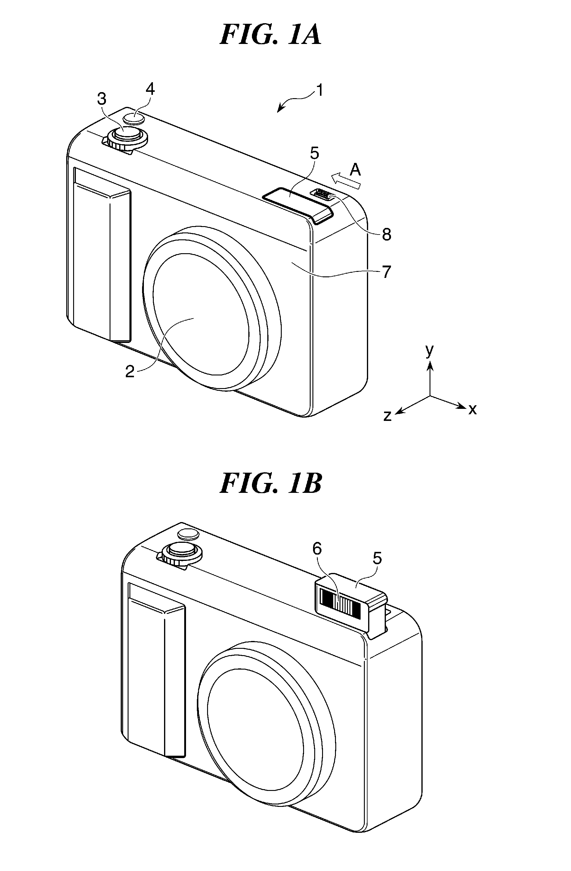
[0024]FIGS. 1A and 1B are perspective views showing an appearance of the digital camera 1 according to the first embodiment. FIG. 1A shows a state in which a movable portion (a portion that is movable with respect to a camera body in a state where the electronic flash unit is retracted in the camera body and will hereafter referred to as “the electronic flash movable portion”) 5 of the electronic flash unit is retracted in the camera body. FIG. 1B shows a state in which the electronic flash movable portion 5 has popped out (projected) from the camera body a...

second embodiment

[0051]FIG. 7 is a y-z cross-sectional view showing an electronic flash unit, which a digital camera has, roughly in a central part thereof, and shows a state in which the first stopper portion 10a is in abutment with a first elastic member 41 while the electronic flash movable portion 5 is popping up. The first elastic member 41 has a double-layer structure comprised of a first layer 41a and a second layer 41b which are made of different materials and laid on top of one another. A material (such as sponge) whose elastic coefficient is lower (that is, repulsive force is smaller) and silencing performance is higher as compared to the second layer 41b is used for the first layer 41a with which the first stopper portion 10a is in abutment. A material (such as silicon rubber) whose silencing performance is lower but deteriorates to a smaller degree in a low-temperature environment as compared to the first layer 41a is used for the second layer 41b.

[0052]As is the case with the first em...

third embodiment

[0054]A description will now be given of a rotary type light-emitting apparatus which is rotatively moved between a retracted position and a light-emitting position. Here, the light-emitting apparatus is formed as one unit, but the following description will be given only of schematic arrangement of an electronic flash movable portion and portions relating to movement of an electronic flash movable portion between the retracted position and the light-emitting position.

[0055]FIGS. 8A and 8B are y-z cross-sectional views of an electronic flash unit, which a digital camera according to the third embodiment has, in roughly a central part thereof, in which FIG. 8A shows a state in which the electronic flash movable portion 50 lies in the retracted position, and FIG. 8B shows a state in which the electronic flash movable portion 50 lies in the light-emitting position.

[0056]The rotary-type electronic flash movable portion 50 is urged by a spring (not shown) in a direction in which a light...


PUM


Abstract

A light-emitting apparatus which is capable of, even when an environmental temperature changes, stably reducing collision noise, vibration noise, and so on generated when the light-emitting apparatus moves from a retracted position to a light-emitting position. A movable portion has a first stopper portion coming into abutment with a first elastic member when the movable portion moves from the retracted position to the light-emitting position, and a second stopper portion coming into abutment with a second elastic member with a higher elastic coefficient than the first elastic member when the movable portion moves from the retracted position to the light-emitting position. When the movable portion moves from the retracted position to the light-emitting position, the first stopper portion comes into abutment with the first elastic member, deforming the first elastic member by a predetermined amount, and then the second stopper portion comes into abutment with the second elastic member.

Description

BACKGROUND OF THE INVENTION[0001]1. Field of the Invention[0002]The present invention relates to an image pickup apparatus having a light-emitting apparatus capable of moving between a retracted position and a light-emitting position, and in particular to a technique of reducing impact when the light-emitting apparatus stops at the light-emitting position in a case where the light-emitting apparatus is moved from the retracted position to the light-emitting position using a tension of an elastic member.[0003]2. Description of the Related Art[0004]There is known an image pickup apparatus having a light-emitting apparatus (hereafter referred to as “the electronic flash”) capable of moving between a retracted position and a light-emitting position. As an example of a method to move the electronic flash, there is known a motor drive system that moves the electronic flash by a gear connected to a motor as a drive source. As another example of a method to move the electronic flash, there ...

Claims


Application Information

Patent Timeline
IPC IPC(8): G03B15/02G03B19/02
CPCF21L15/02G03B19/02G03B15/05G03B2215/0507F21L4/00G03B15/03
Inventor FURUTA, TAKASHI
Owner CANON KK
Why Eureka
Try Eureka