Indirect media flatness measurement

a technology of indirect media and flatness measurement, applied in the direction of printing, other printing apparatus, etc., can solve the problems of insufficient flatness of sheets in printing zones, inability to hold media flatness past the ink jet aperture printing array, and difficulty in printing head-to-media tolerances

Inactive Publication Date: 2014-01-23
XEROX CORP
View PDF2 Cites 12 Cited by
  • Summary
  • Abstract
  • Description
  • Claims
  • Application Information

AI Technical Summary

Problems solved by technology

However, these tight printhead-to-media tolerances pose a challenge for any cut sheet printer, since the cut sheet body is generally not perfectly flat.
However, sheets may not be held sufficiently flat in the printing zone, to the extent that a shutdown of the printer would be necessary to avoid the media contacting the printheads.
A known difficulty in the technology is that the presumption of media flatness past the ink jet aperture printing array may not hold.
However, without the ability to measure the flatness of the media in the printing zone, the necessary amount of hold-down force is subject to some speculation.
In order to overcome this, the hold-down force is intentionally over-applied, which is at least a source of inefficiency.

Method used


Image

  • Indirect media flatness measurement
  • Indirect media flatness measurement
  • Indirect media flatness measurement

Examples


Embodiment Construction

Introduction

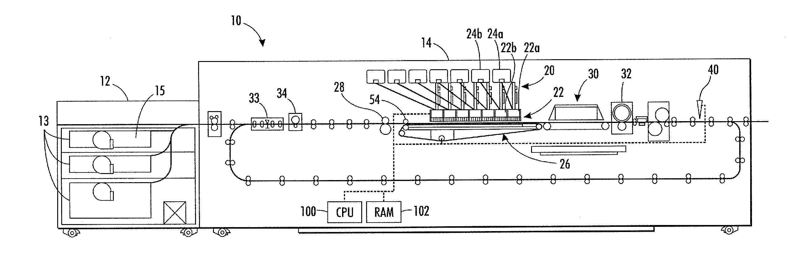
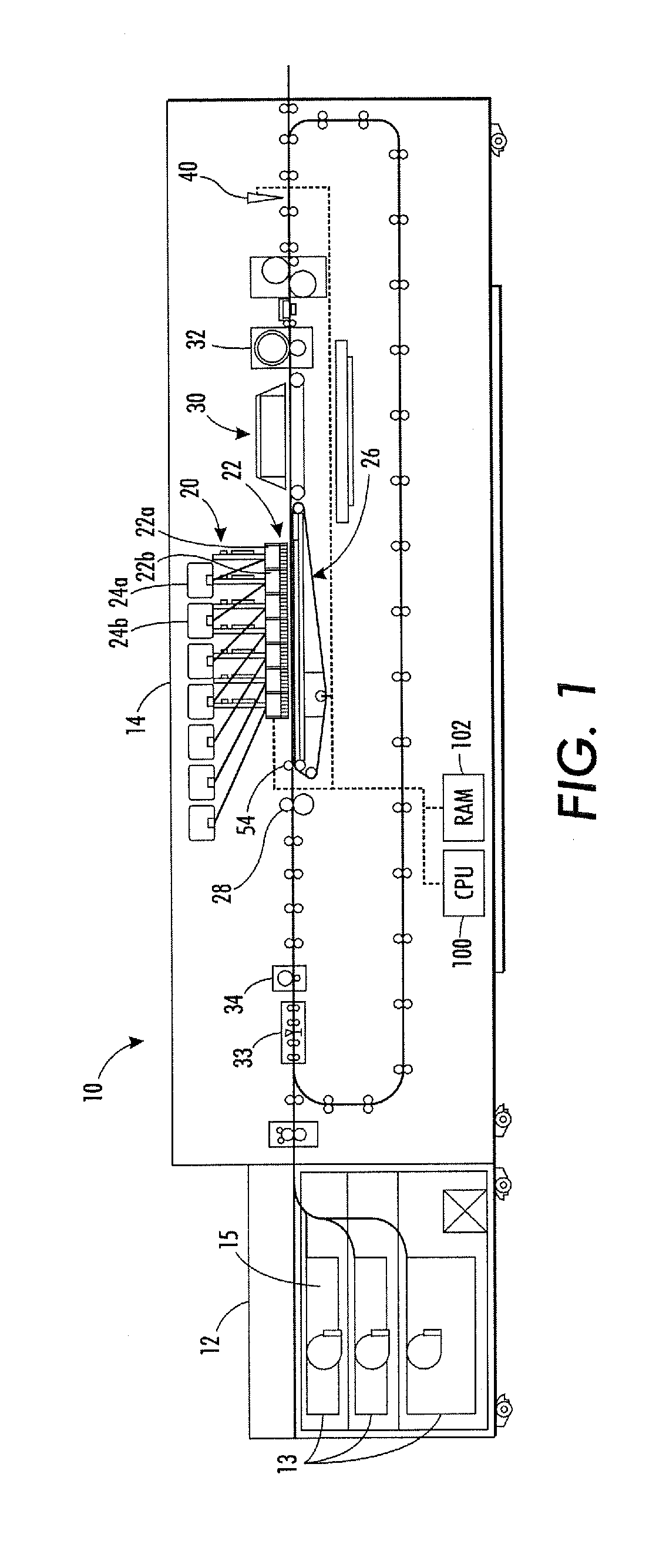
[0027]As used herein, a “printer” refers to any device, machine, apparatus, and the like, for forming images on substrate media using ink, toner, and the like. A “printer” can encompass any apparatus, such as a copier, bookmaking machine, facsimile machine, multi-function machine, etc., which performs a print outputting function for any purpose. Where a monochrome printer is described, it will be appreciated that the disclosure can encompass a printing system that uses more than one color (e.g., red, blue, green, black, cyan, magenta, yellow, clear, etc.) ink or toner to form a multiple-color image on a substrate media.

[0028]As used herein, “substrate media” refers to a tangible medium, such as paper (e.g., a cut sheet of paper, a continuous web of paper, a ream of paper, etc.), transparencies, parchment, film, fabric, plastic, vellum, paperboard, up to between about 26 and 29 point (i.e., about 0.026-0.029 in. thickness), or other substrates on which an image can be pri...


PUM


Abstract

An indirect media flatness measurement system, and method, by which the appropriate level of hold-down force may be determined with some degree of quantitative accuracy. In an ink jet printer that is operative to subject a substrate media to a hold down force during printing, the method including printing a predetermined test image having a predetermined pattern on a substrate media using an ink jet print apparatus to produce a test print. Optionally, pattern may be an array of test symbols. The test symbol may comprise a line printed on the substrate media in a direction perpendicular to a process direction of the printer. The test print is compared with the predetermined test image, including measuring drop placement errors of test symbols. The height of the substrate media at the location of each test symbol is calculated based upon the drop placement error.

Description

BACKGROUND[0001]1. Field of the Disclosure[0002]The present disclosure relates to methods of document creation. More specifically, the present disclosure is directed to a method and apparatus for indirectly measuring the flatness of a substrate media upon which an image is printed by an ink jet print system.[0003]2. Brief Discussion of Related Art[0004]In certain printers using ink jet technology, it is expected that inks, e.g., solid inks, UV inks, aqueous inks, and functional inks including those used in 3D printing application or printed electronics, among others, will be jetted directly onto substrate media, often a cut sheet. A critical parameter in this printing process is the size of the printhead-to-media gap. In certain current technology, the gap is set as small as 0.5 mm in order to minimize the pixel placement errors due to misdirected jets. For other printheads, for example those having relatively higher drop velocity, it is possible that the gap can be opened to betwee...

Claims


Application Information

Patent Timeline
Patent Type & Authority Applications(United States)
IPC IPC(8): B41J29/393
CPCB41J11/0035B41J11/0095B41J2203/011B41J2/04556B41J29/393
Inventor LI, FAMINGZHOU, JINGXU, FUSHENGELLIOT, JACK GAYNOR
Owner XEROX CORP
Why Eureka
Try Eureka