
Navigation signal transmitter and method for generating navigation signal

a technology of navigation signal and transmitter, which is applied in the direction of synchronisation transmitter, digital transmission, instruments, etc., can solve the problems of high equipment cost, large size, and high oscillator cost, and achieve the effect of reducing the frequency deviation of terrestrially transmitted navigation signals, reducing the use of high-precision and expensive, and improving convenien

Inactive Publication Date: 2014-01-16
GNSS TECH INC +1
View PDF0 Cites 8 Cited by
  • Summary
  • Abstract
  • Description
  • Claims
  • Application Information

AI Technical Summary

Benefits of technology

The navigation signal transmitter and method described in this patent make it possible to reduce costs and improve the accuracy of satellite navigation signals. They do this by eliminating the need for expensive and high-precision oscillators that are normally required in conventional transmitters. Additionally, the system helps to speed up signal acquisition time by matching timings among multiple navigation signals.

Problems solved by technology

Generally, oscillators having these characteristic features are strictly managed and controlled in temperature in thermostatic chambers and could be replaced with atomic clocks in which resonance of an atom having some particular frequency is used, resulting in being accompanied by disadvantages of high equipment expenses as well as large size.
Furthermore, how expensive the oscillator is, frequency variations are certainly be caused resulting from a long term use.
Therefore, there is an undesirable need for regular frequency calibration.
However, although the GPS signal can be easily received in the open air environment, there is the problem that the GPS signal cannot be received since it is hardly reachable in an indoor environment such as buildings and underground shopping areas.

Method used


Image

  • Navigation signal transmitter and method for generating navigation signal
  • Navigation signal transmitter and method for generating navigation signal
  • Navigation signal transmitter and method for generating navigation signal

Examples


embodiment 1

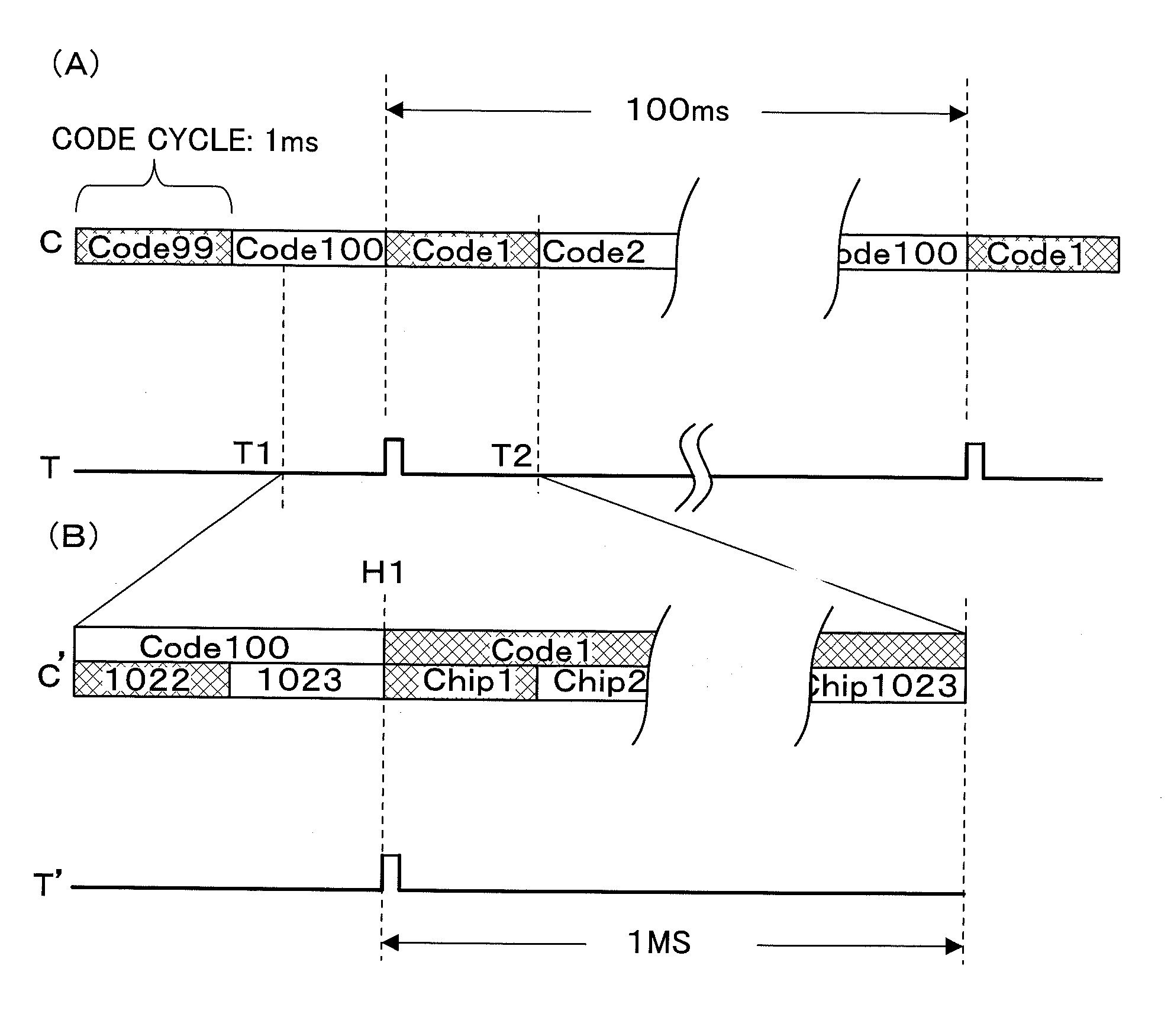
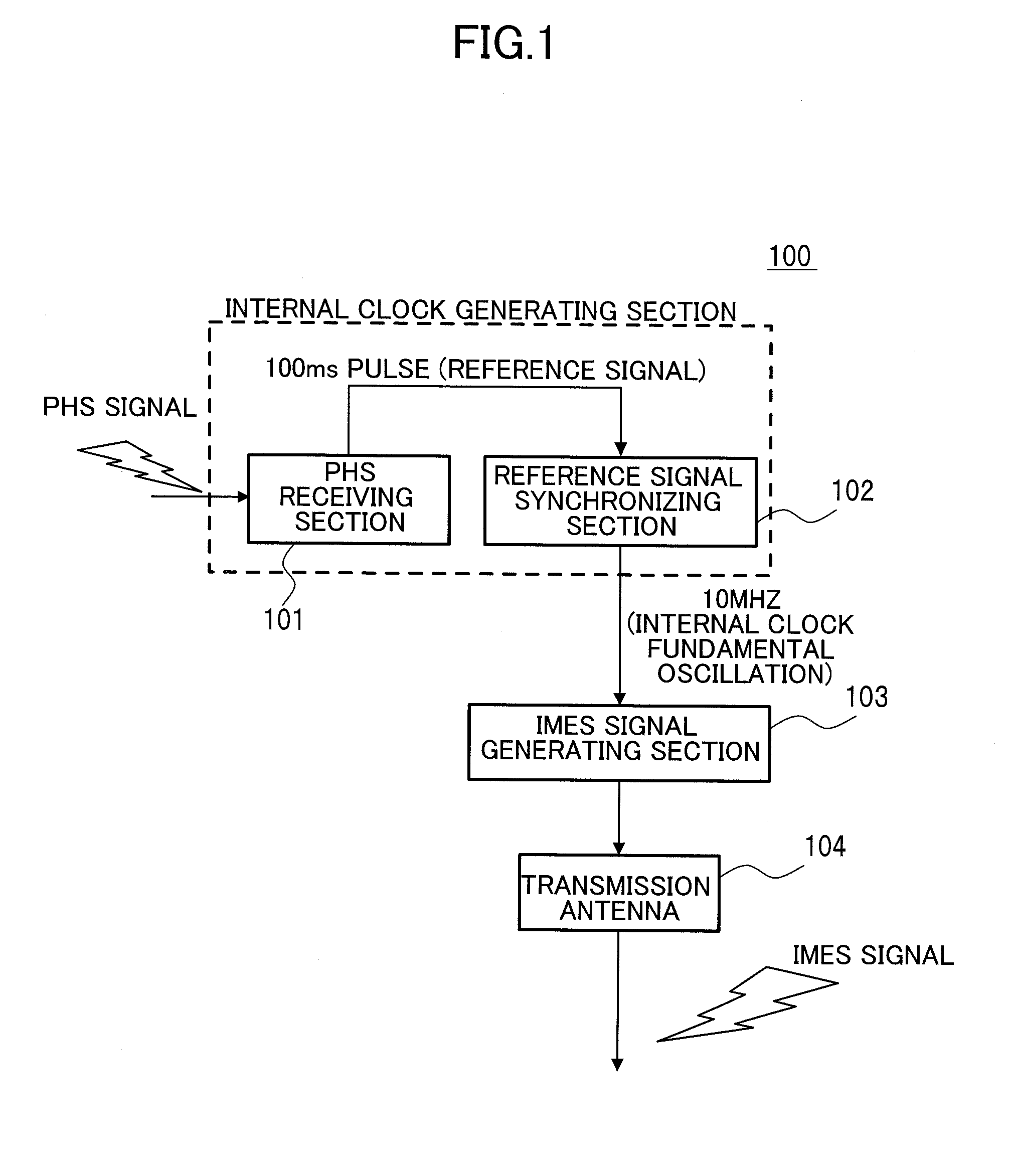
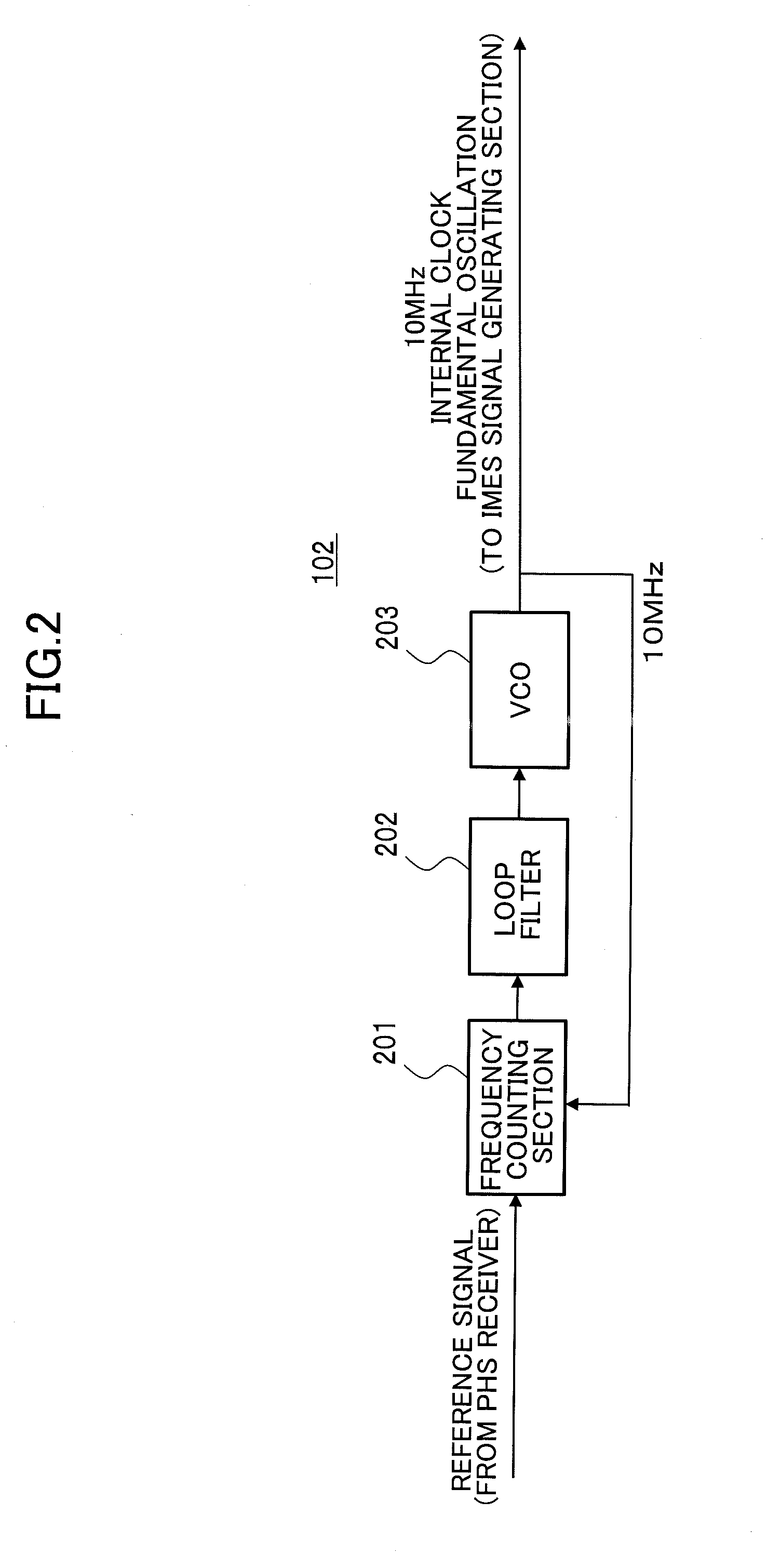
[0042]FIG. 1 illustrates a structure of a navigation signal transmitter according to an embodiment of the present invention. Here, it is assumed in this embodiment that a PHS signal shall be “some kind of signal of an external system (transmission wave)”. The navigation signal transmitter 100 comprises a PHS receiving section 101, a reference signal synchronizing section 102, an IMES signal generating section 103 and a transmission antenna 104. In addition, the PHS receiving section 101 and the reference signal synchronizing section 102 make up an internal clock generating section (which just corresponds to the internal clock generator 231 illustrated in FIG. 2 of Patent Document 1). However, in conventional internal clock generators such as illustrated in FIG. 2 of Patent Document 1, an expensive OCXO (Oven Controlled Xtal Oscillator, which is also called a “temperature controlled crystal oscillator”), for example, is employed in order to secure a high degree of frequency precision...

embodiment 2

[0054]FIG. 5A illustrates, as a second embodiment of the present invention, a structure of the reference signal synchronizing section for making time synchronization in the navigation signal transmitter. A reference signal synchronizing unit 500 comprises a phase comparing section 501, a loop filter 502, a VCO (Voltage Controlled Oscillator) 503 and a frequency divider 504.

[0055]In the phase comparing section 501, a phase difference is measured by using a signal output from the PHS receiving section as a reference signal of the reference signal synchronizing unit to perform a phase comparison with a signal generated by the frequency divider 504 in a PLL section. The measured phase difference is subjected to smoothing in the loop filter 502, converted to a direct current voltage through D / C conversion with an appropriate gain setting, and input to VOC 503. This direct current voltage is proportional to the phase difference between the reference and frequency divided signals, so that ...

embodiment 3

[0058]FIG. 7 illustrates, as a third embodiment of the present invention, a structure for which a radio wave of a mobile phone such as GSM and LTE is employed as some kind of signal of an external system. A navigation system signal transmitter 700 comprises a GSM or an LTE receiving section (designated generically as a receiving section 701) for receiving a GSM signal or an LTE signal, a reference signal synchronizing section 702, an IMES signal generating section 703 and a transmission antenna 704. That is, in this embodiment, the GSM or the LTE receiving section 701 is employed in place of the PHS receiving section 101 to input pulses of 10 ms, 100 ms or 1000 ms as a reference signal to the reference signal synchronizing section 702. It is only necessary in a modification of the reference signal synchronizing section 702 to change the value to be compared with the number of pulses counted by a frequency counter (not shown in FIG. 7) to 10 ms, 100 ms or 1000 ms without requiring an...


PUM


Abstract

Provided is a navigation signal transmitter capable of ensuring reduction in frequency deviation of a terrestrially transmitted navigation signal at low cost. The navigation signal transmitter is operable to receive a transmission wave, generate a synchronization pulse in synchronization with a predetermined data frame, generate an internal clock fundamental oscillation by a reference signal synchronizing section (550) using the synchronization pulse as a reference signal, generate an IMES signal based on the internal clock fundamental oscillation, and transmit the IMES signal. The reference signal synchronizing section (550) comprises a counter circuit (551), a comparator (553), a low-pass control filter (554), a D / A converter (555) and a voltage controlled oscillator (556). The reference signal synchronizing section (550) is configured to, when a magnitude relationship between the number of clock pulses generated in the voltage controlled oscillator (556) using the synchronization pulse as the reference signal and a reference value falls within a predetermined value and continues a predetermined number of times in one direction, adjust a level of control voltage of the voltage controlled oscillator (556).

Description

TECHNICAL FIELD[0001]The present invention relates to a ground-based navigation signal transmitter for transmitting a navigation signal or a signal for positioning a receiver and a method for generating a navigation signal.BACKGROUND ART[0002]In satellite positioning system, a position of a receiver is determined by passively measuring positioning signals transmitted from a plurality of satellites by the receiver. In this case, time synchronization is one of key technical elements. An onboard clock is used for generation of a regular, generally sequential, series of events, called “epoch”, and a clock time of occurrence of the epoch is coded to a random number code or a pseudo-random number code (hereinafter, referred to as a spreading code). Then, as a result of the pseudo-random number or random number function of a time-epoch coding sequence, an output signal spectrum is determined according to a rate of change of a spread code element and a waveform of a spreading signal. The fr...

Claims


Application Information

Patent Timeline
Patent Type & Authority Applications(United States)
IPC IPC(8): H04L7/00
CPCH04L7/0091G01S1/20G01S19/10G01S19/11G01S5/021G01S5/0226G01C21/28G01S19/31G01S19/42
Inventor TORIMOTO, HIDEYUKIISHII, MAKOTOASAKO, MASAHIROMAEDA, HIROAKI
Owner GNSS TECH INC
Learn More