Cascade refrigeration cycle apparatus
a technology of cavern and cycle apparatus, which is applied in the direction of refrigeration safety arrangement, refrigeration components, light and heating apparatus, etc., to achieve the effect of suppressing an excessive rise in the high pressure of the refrigeran
- Summary
- Abstract
- Description
- Claims
- Application Information
AI Technical Summary
Benefits of technology
Problems solved by technology
Method used
Image
Examples
first embodiment
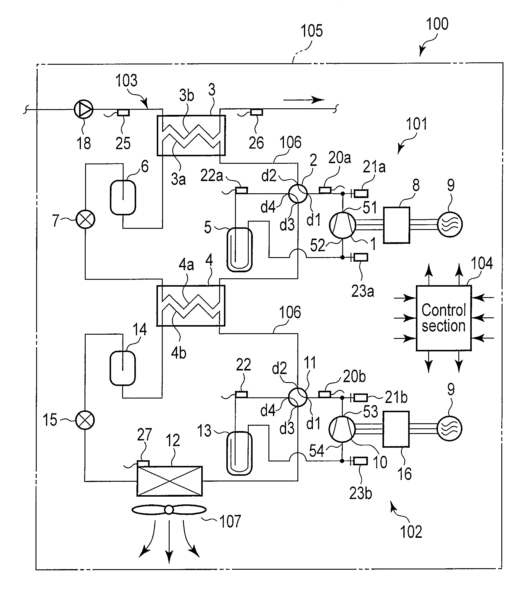
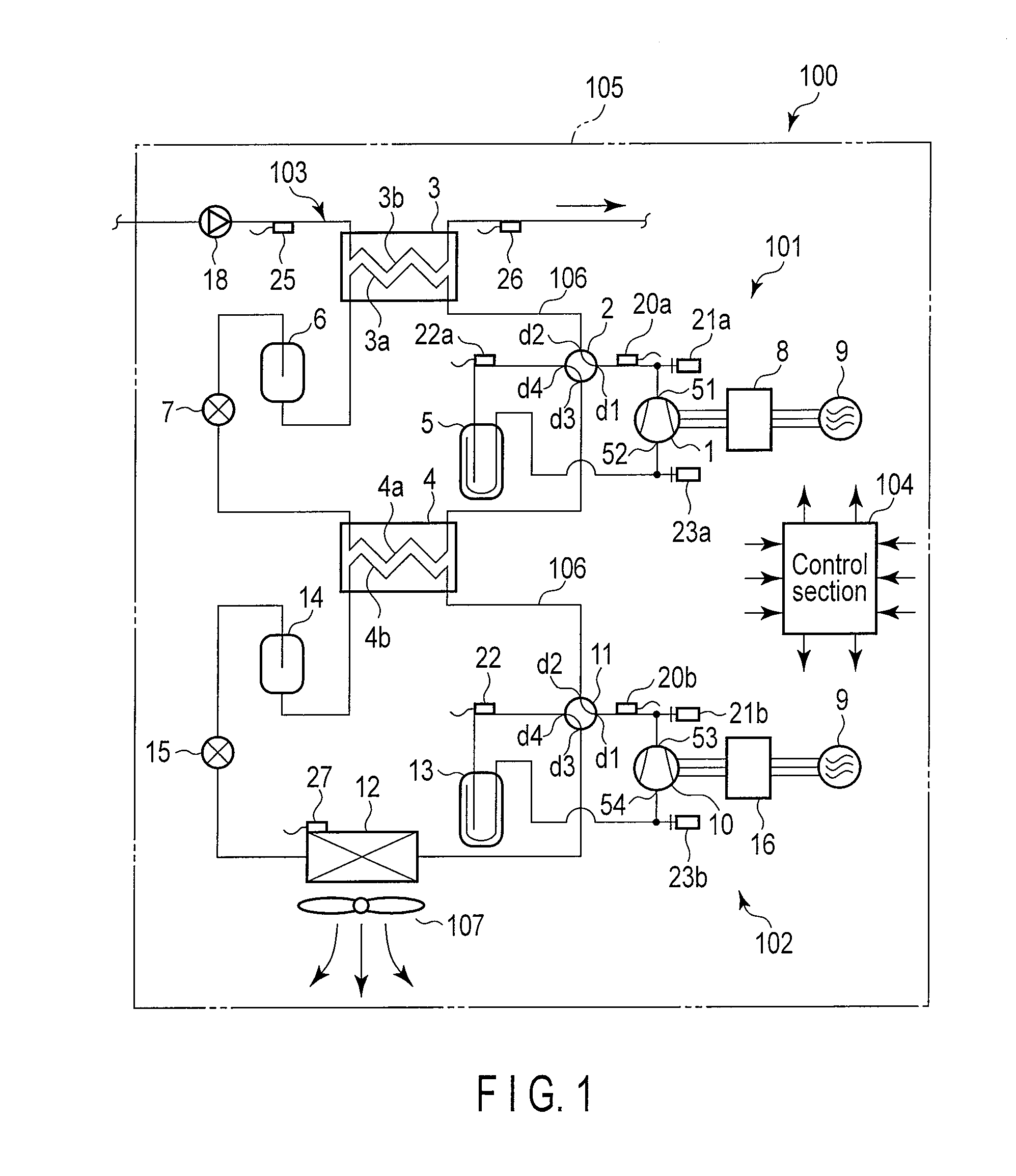
[0020]FIG. 1 is a diagram of a refrigeration cycle configuration of a cascade refrigeration cycle apparatus 100 used as a hot water supply system according to a
[0021]The cascade refrigeration cycle apparatus 100 used as a hot water supply system comprises a high-temperature-side refrigeration circuit 101, a low-temperature-side refrigeration circuit 102, hot water piping 103, and a control section (control means) 104 which are mounted in an identical housing 105.
[0022]In the high-temperature-side refrigeration circuit 101, a discharge section 51 of a high-temperature-side compressor 1 is connected to a first port d1 of a four-way selector valve 2 via refrigerant piping 106. A primary-side channel 3a in a water heat exchanger 3 is connected to a second port d2 of the four-way selector valve 2 via the refrigerant piping 106. A third port d3 of the four-way selector valve 2 is connected to a primary-side channel 4a in a cascade heat exchanger 4 via the refrigerant piping 106.
[0023]A fo...
second embodiment
[0068]A main feature of the cascade refrigeration cycle apparatus 100 is that the high-temperature-side compressor 1 used for the high-temperature-side refrigeration circuit 101 uses a constant-speed compressor 1A with an operating frequency depending on the power supply frequency. When a refrigeration cycle operation is started, the high-temperature-side compressor 1A performs a constant-speed operation. The control section 104 performs inverter control on the low-temperature-side compressor 10 to set the operating frequency for the low-temperature-side compressor 10 lower than the operating frequency for the high-temperature-side compressor 1A in a controllable manner.
[0069]This allows prevention of a possible excessive increase in the high-pressure-side pressure in the low-temperature-side refrigeration circuit 102. Alternatively, in contrast, inverter control may be performed exclusively on the high-temperature-side compressor 1A, with the low-temperature-side compressor 10 ope...
fourth embodiment
[0097]FIG. 5 is a diagram of a refrigeration cycle configuration of a cascade refrigeration cycle apparatus complex 200 applied to a hot water supply system according to a
[0098]The cascade refrigeration cycle apparatus complex 200 comprises a plurality of (two) cascade refrigeration cycle apparatuses 100 according to the first embodiment described above connected together in series along the hot water piping 103 and accommodated in an identical housing 201. Each of the cascade refrigeration cycle apparatuses 100 uses the same components as those of the first embodiment. The components are denoted by the same reference numbers and will not be newly described.
[0099]In the cascade refrigeration cycle apparatus complex 200, when the plurality of cascade refrigeration cycle apparatuses 100 is simultaneously actuated to start the refrigeration cycle operation, a surge current flows through the inverter apparatuses 8 and 16 and temporarily increases. In some cases, the power supply capacit...
PUM
 Abstract
Description
Claims
Application Information
 - R&D
- Intellectual Property
- Life Sciences
- Materials
- Tech Scout
- Unparalleled Data Quality
- Higher Quality Content
- 60% Fewer Hallucinations
Browse by: Latest US Patents, China's latest patents, Technical Efficacy Thesaurus, Application Domain, Technology Topic, Popular Technical Reports.
© 2025 PatSnap. All rights reserved.Legal|Privacy policy|Modern Slavery Act Transparency Statement|Sitemap|About US| Contact US: help@patsnap.com


