
Enclosing device and a medical imaging device having the enclosing device

Inactive Publication Date: 2014-01-09
SIEMENS AG
View PDF7 Cites 6 Cited by
  • Summary
  • Abstract
  • Description
  • Claims
  • Application Information

AI Technical Summary

Benefits of technology

The invention is a noise and vibration damping enclosing shell for medical imaging devices, particularly magnetic resonance devices. The enclosing shell has a receiving chamber that can be filled with a specific gas or liquid to achieve improved noise and vibration damping. The receiving chamber can be emptied during maintenance work and replaced with another filler element. The enclosing shell also has an outlet opening with a valve element to prevent negative pressure and allow air to flow in and out. The double-walled enclosing shell unit has a constant distance between the two enclosing shells, regardless of the filler element inside the receiving chamber, which maintains a consistent noise and vibration damping property. The plurality of spacing elements fixes the enclosing shells at a high rigidity and low net weight.

Problems solved by technology

When in operation, magnetic resonance devices generate high levels of operating noise which can have an unpleasant effect on a patient contained in a receiving area of the magnetic resonance device for the purpose of an examination.
Said high operating noise levels are generated inside a magnet unit of the magnetic resonance device as a result of an interaction of a gradient unit with a magnet.
However, heavy enclosing devices are disadvantageous with regard to assembly and / or installation, such as in a service situation and / or for maintenance activities.
For assembly and / or installation convenience, the enclosing devices should be embodied in the most lightweight form possible, though in most cases enclosing devices of said type have poor noise attenuating properties.

Method used


Image

  • Enclosing device and a medical imaging device having the enclosing device
  • Enclosing device and a medical imaging device having the enclosing device
  • Enclosing device and a medical imaging device having the enclosing device

Examples


Embodiment Construction

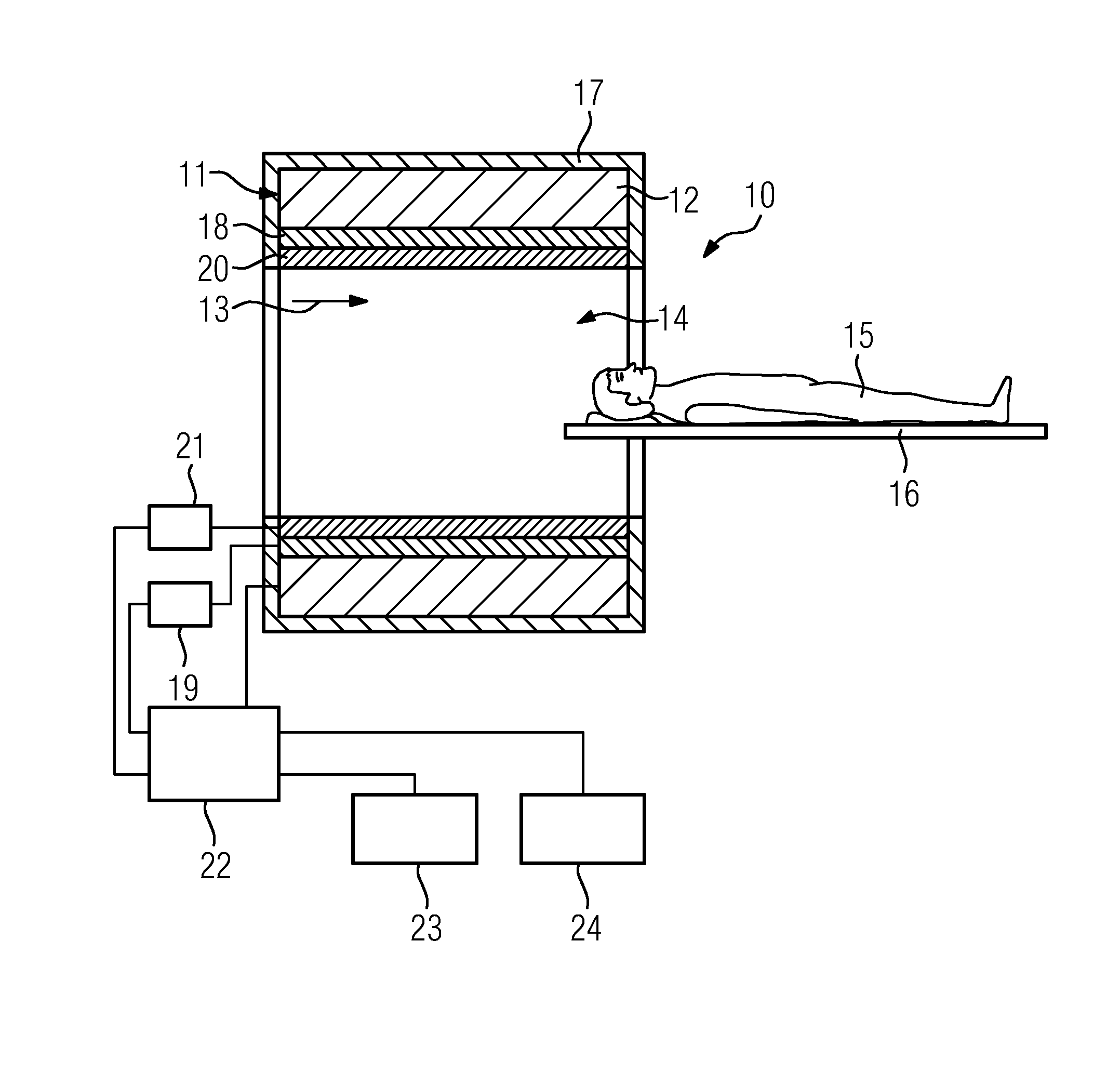
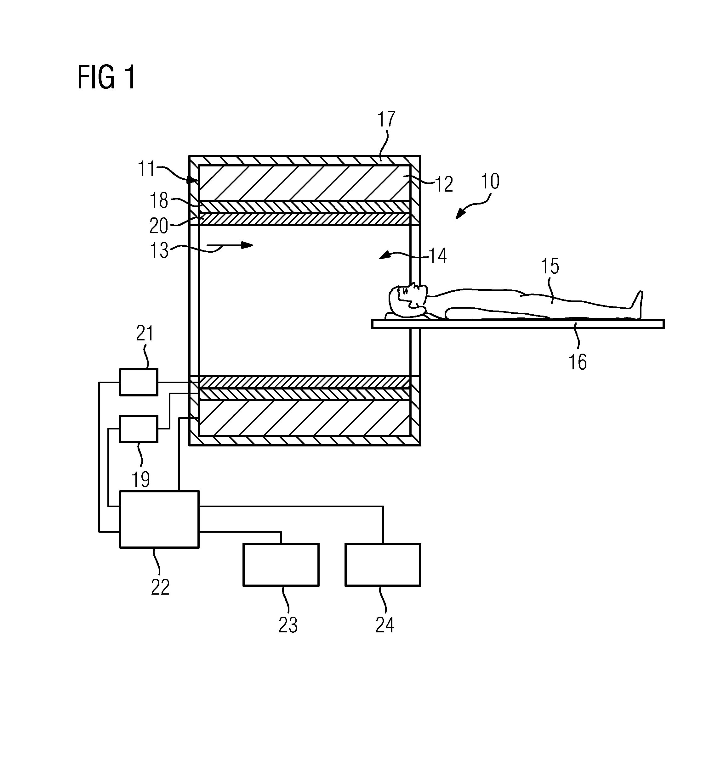
[0023]FIG. 1 shows a schematic view of an inventive medical imaging device that is formed by a magnetic resonance device 10. Furthermore, the medical imaging device can also be formed by an imaging device comprising a magnetic resonance device 10, such as an MR-PET device for example.

[0024]The magnetic resonance device 10 comprises a magnet unit 11 having a main magnet 12 for generating a strong and in particular constant main magnetic field 13. The magnetic resonance device 10 also has a cylinder-shaped receiving area 14 for accommodating a patient 15, the receiving area 14 being enclosed by the magnet unit 11 in a circumferential direction. The patient 15 can be introduced into the receiving area 14 by means of a patient couch 16 of the magnetic resonance device 10. For this purpose the patient couch 16 is arranged so as to be movable within the magnetic resonance device 10. In addition the magnetic resonance device 10 has a housing unit 17 surrounding the magnet unit 11.

[0025]The...


PUM


Abstract

An enclosing device, in particular for a magnetic resonance device, includes at least one first enclosing shell and at least one second enclosing shell. The enclosing device has a double-walled enclosing shell unit which comprises the first enclosing shell and the second enclosing shell.

Description

CROSS REFERENCE TO RELATED APPLICATIONS[0001]The present application claims priority to German Patent Office application No. 10 2012 211715.6 DE filed Jul. 5, 2012, the entire content of which is hereby incorporated herein by reference.FIELD OF INVENTION[0002]The present invention relates to an enclosing device, in particular for a medical imaging device, comprising at least one first enclosing shell and at least one second enclosing shell.BACKGROUND OF INVENTION[0003]When in operation, magnetic resonance devices generate high levels of operating noise which can have an unpleasant effect on a patient contained in a receiving area of the magnetic resonance device for the purpose of an examination. Said high operating noise levels are generated inside a magnet unit of the magnetic resonance device as a result of an interaction of a gradient unit with a magnet. Sound is transmitted inside the magnetic resonance device in this case as a result of airborne sound excitation as well as by ...

Claims


Application Information

Patent Timeline
IPC IPC(8): F16F7/00
CPCF16F7/00G01R33/3802G01R33/3854G10K11/168
Inventor EBERLER, MICHAEL
Owner SIEMENS AG
Learn More