Wireless energy transfer for rechargeable batteries

a rechargeable battery and wireless technology, applied in the direction of transformers, inductances, transportation and packaging, etc., can solve the problem that wireless enabled batteries may not be able to receive sufficient energy, and achieve the effect of low coupling

Active Publication Date: 2014-01-02
WITRICITY CORP
View PDF2 Cites 215 Cited by
  • Summary
  • Abstract
  • Description
  • Claims
  • Application Information

AI Technical Summary

Benefits of technology

[0007]A wireless energy transfer enabled battery includes a resonator. In one aspect the resonator is positioned asymmetrically in a battery sized enclosure such that when two wirelessly enabled batteries are placed in close proximity the resonators of the two batteries have low coupling.

Problems solved by technology

However, resonators placed next to, near, or in close proximity to each other may interact or affect each other's parameters, characteristics, wireless energy transfer performance, and the like.
In such devices, without special consideration the wireless enabled batteries may not be able to receive sufficient energy due to the perturbations on the resonators from other batteries.

Method used


Image

  • Wireless energy transfer for rechargeable batteries
  • Wireless energy transfer for rechargeable batteries
  • Wireless energy transfer for rechargeable batteries

Examples


Embodiment Construction

Wireless Battery Configurations

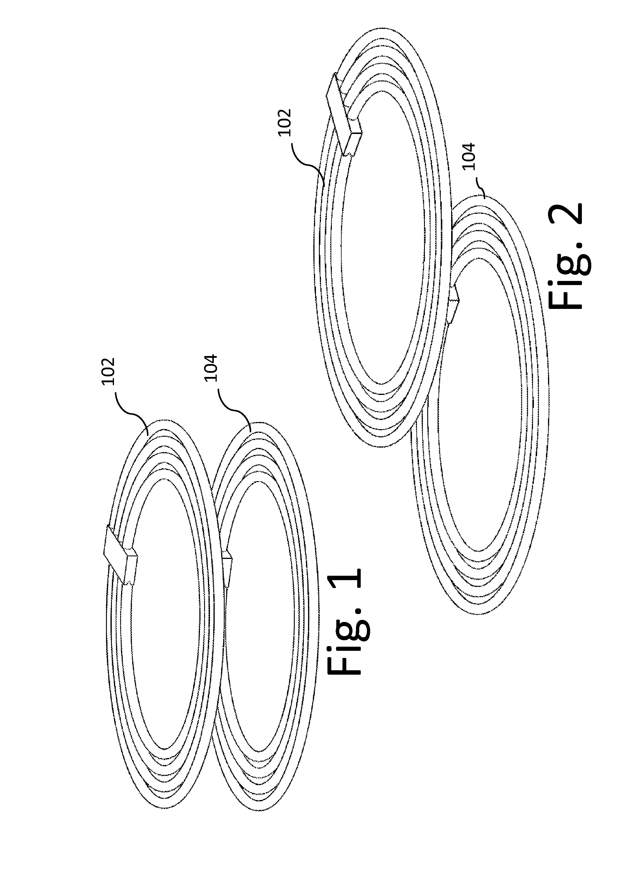
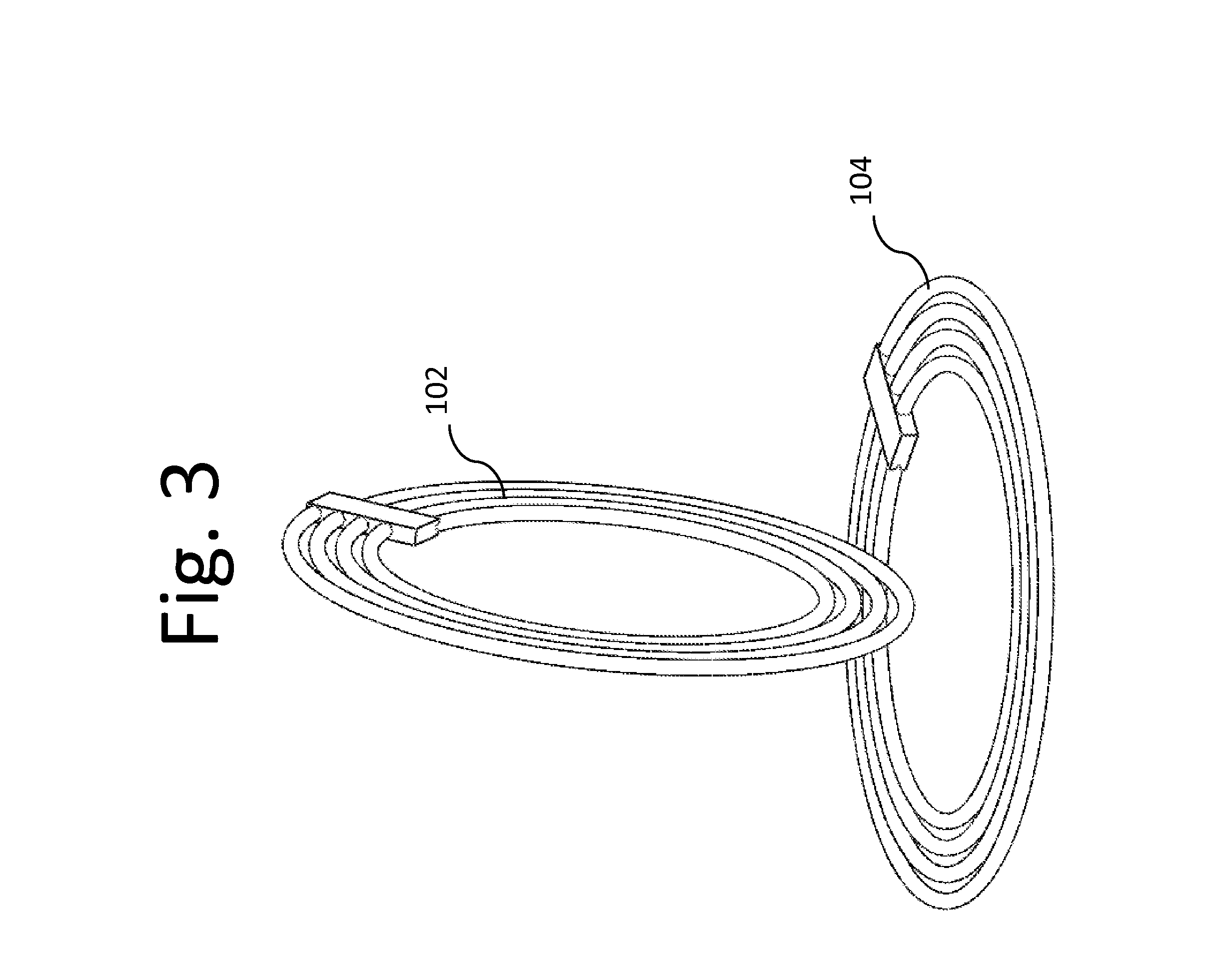
[0021]Resonators and electronics may be integrated or located next to batteries enabling wireless energy transfer to the batteries allowing wireless charging of the battery packs. With the addition of resonators and control circuitry, batteries and battery packs may wirelessly capture energy from a source and recharge without having to be precisely positioned in a charger. The wireless batteries and battery packs may be wirelessly recharged inside the host device from an external wireless power source without requiring that the device be physically plugged into an external energy supply.

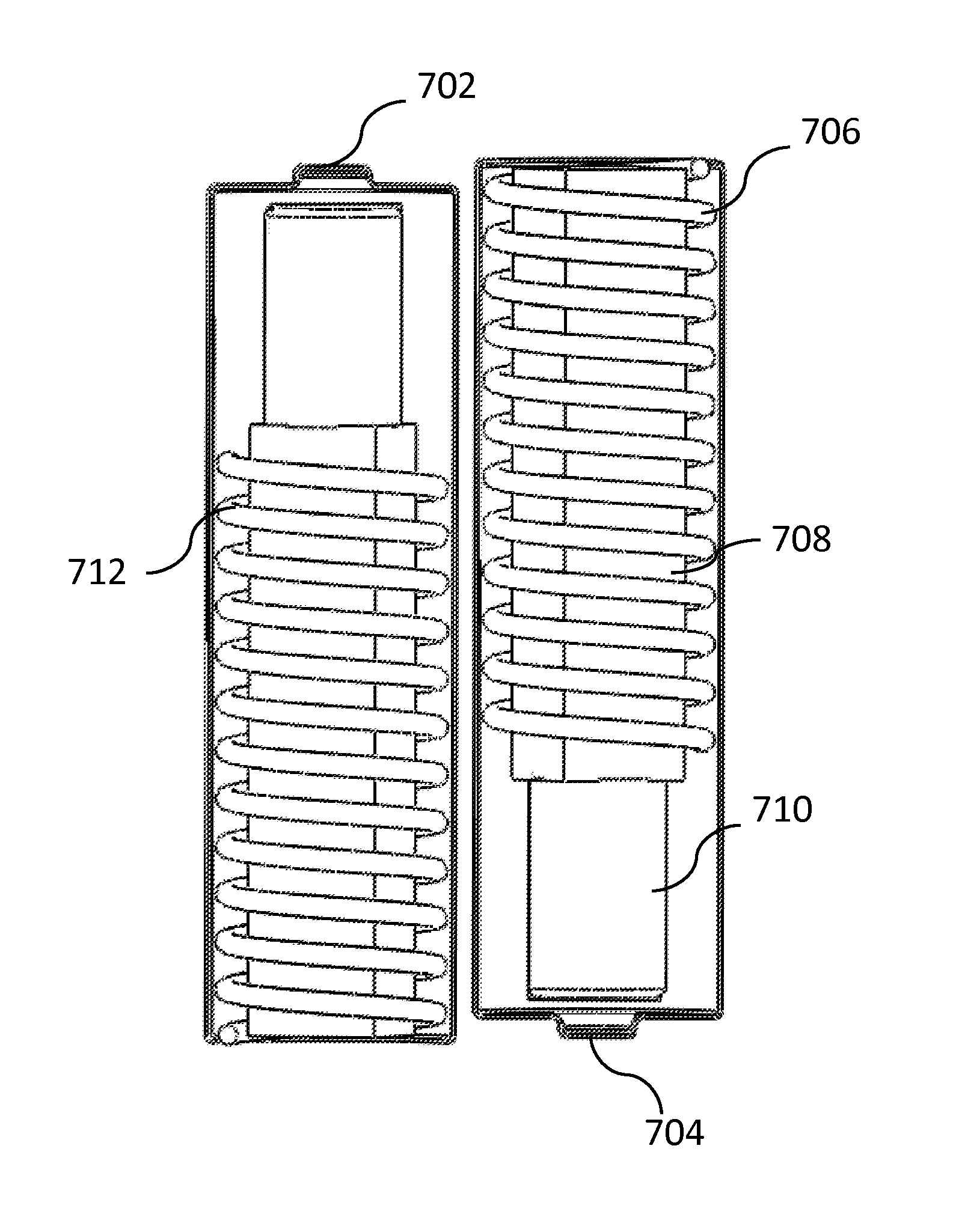
[0022]FIG. 6 shows one example of a wireless battery comprising a magnetic resonator. The example battery comprises a resonator coil 606 wrapped around an optional block of magnetic material 608. The block of magnetic material 608 may be hollow and may house power and control circuitry (not shown) and optionally a rechargeable battery 604 which may be recharged by the e...


PUM


Abstract

A wireless energy transfer enabled battery includes a resonator that is positioned asymmetrically in a battery sized enclosure such that when two wirelessly enabled batteries are placed in close proximity the resonators of the two batteries have low coupling.

Description

BACKGROUND[0001]1. Field[0002]This disclosure relates to wireless energy transfer to batteries and apparatus to accomplish such transfer.[0003]2. Description of the Related Art[0004]Energy or power may be transferred wirelessly using a variety of known radiative, or far-field, and non-radiative, or near-field, techniques as detailed, for example, in commonly owned U.S. patent application Ser. No. 12 / 613,686 published on May 6, 2010 as US 2010 / 010909445 and entitled “Wireless Energy Transfer Systems,” U.S. patent application Ser. No. 12 / 860,375 published on Dec. 9, 2010 as 2010 / 0308939 and entitled “Integrated Resonator-Shield Structures,” U.S. patent application Ser. No. 13 / 222,915 published on Mar. 15, 2012 as 2012 / 0062345 and entitled “Low Resistance Electrical Conductor,” U.S. patent application Ser. No. 13 / 283,811 published on ______ as ______ and entitled “Multi-Resonator Wireless Energy Transfer for Lighting,” the contents of which are incorporated by reference.[0005]Resonator...

Claims


Application Information

Patent Timeline
Patent Type & Authority Applications(United States)
IPC IPC(8): H02J7/00
CPCH01F38/14H02J50/90H02J50/12H02J50/70
Inventor MCCAULEY, ALEXANDER PATRICKKESLER, MORRIS P.EFE, VOLKANHALL, KATHERINE L.
Owner WITRICITY CORP
Why Eureka
Try Eureka