
Persistent mesh for isolated mobile and temporal networking

a technology of mobile and temporal networks and meshes, applied in the direction of wireless commuication services, network topologies, electrical appliances, etc., can solve the problems of mesh network creation, channel cannot be too small, and certain difficulties are created by wireless mesh networks, so as to facilitate reconnection, maintain a structure to support connectivity within the sub-part, and limit the amount of time a sub-part lacks external network connectivity

Inactive Publication Date: 2013-12-19
DYNAMIC MESH NETWORKS
View PDF8 Cites 5 Cited by
  • Summary
  • Abstract
  • Description
  • Claims
  • Application Information

AI Technical Summary

Benefits of technology

This patent aims to provide a mesh network that is structurally stable and can adapt to changes in its physical environment. The network maintains separate data domains, even when components are added, subtracted, or adjusted. The network also remains connected to external networks, even when they are disconnected. Additionally, the network supports orderly changes in configuration and is capable of joining various previously disparate networks to form a larger structured mesh network.

Problems solved by technology

While wireless mesh networks provide additional functionality not available using other network topologies, certain difficulties are created by wireless mesh networks described in the prior art.
A serious problem for mesh networks is created by the wireless medium used for communication within the mesh.
However, the channels cannot be made too small so as to interfere with one another.
One drawback of ad-hoc mesh is that each access point and client device contends with other access points to use the single communication frequency.
Another drawback is that each access point or node in a simple ad-hoc mesh carries the entire routing table for the mesh network as a whole, and must traverse the table each time a packet arrives in order to know how to process the packet.
As a result of both of these characteristics, when the size of the mesh and the distance between access points increases, performance characteristics of the network decrease dramatically.
As networks grow, each access point's basic service set (BSS) increases to the point where it can become unmanageable.
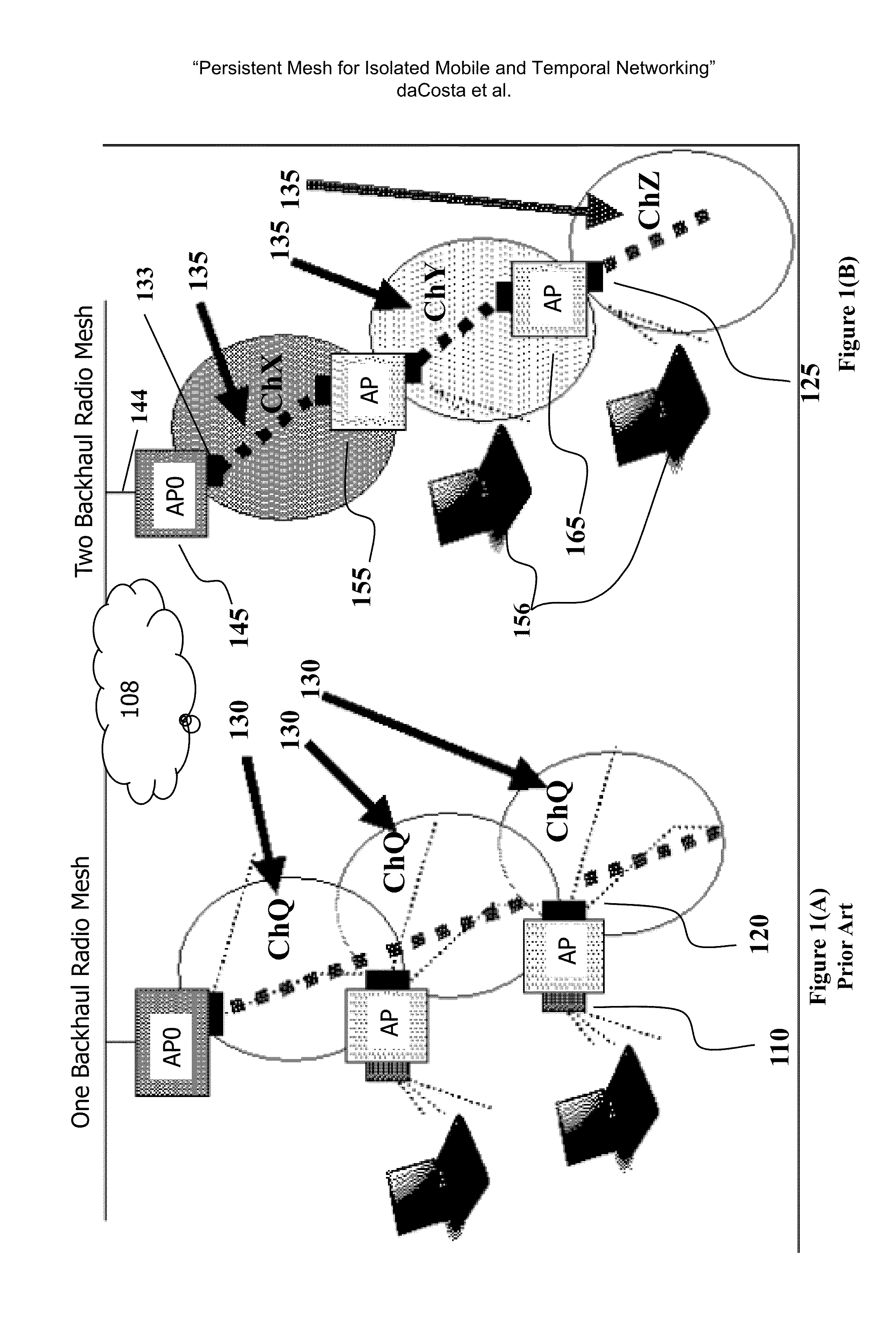
This prior art system, while simple to implement, does not scale beyond a limited number of radios.
Like hubs, single radio mesh backhauls do not scale as well as multi-radio backhauls in addressing high bandwidth requirements for mission critical mesh networks, especially when the single radio solution carries the entire routing table for the mesh in each node.
However, drawbacks exist.
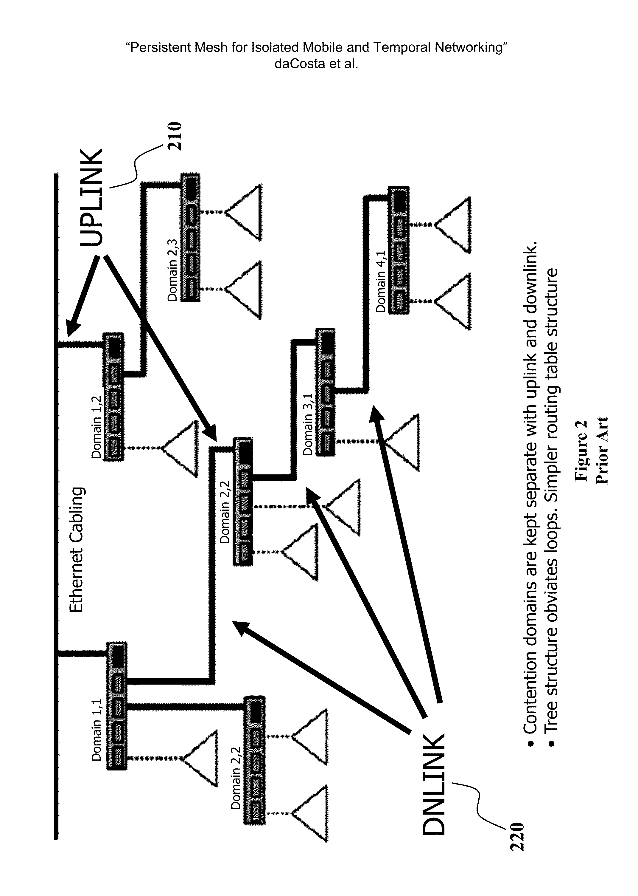
Namely, the prior-art switch architecture has been implemented using physical wireline connections between discrete switches and not a flexible mesh architecture employing wireless connections.
When a group of nodes implemented as such become separated or isolated such that the sub-network does not include a root connection as described above, challenges exist in maintaining a the required tree-like structure.

Method used


Image

  • Persistent mesh for isolated mobile and temporal networking
  • Persistent mesh for isolated mobile and temporal networking
  • Persistent mesh for isolated mobile and temporal networking

Examples


Embodiment Construction

[0041]The foregoing summary, as well as the following detailed description of certain embodiments of the present invention, will be better understood when read in conjunction with the appended drawings.

[0042]In some embodiments of the instant invention, the inter-access point communication occurs using agreed-upon wireless communication protocols, but a mesh may employ any communications means, wired or wireless. Further, one or more of the access points may be connected to an external network whereby client devices in communication with the mesh are capable of accessing the same external network.

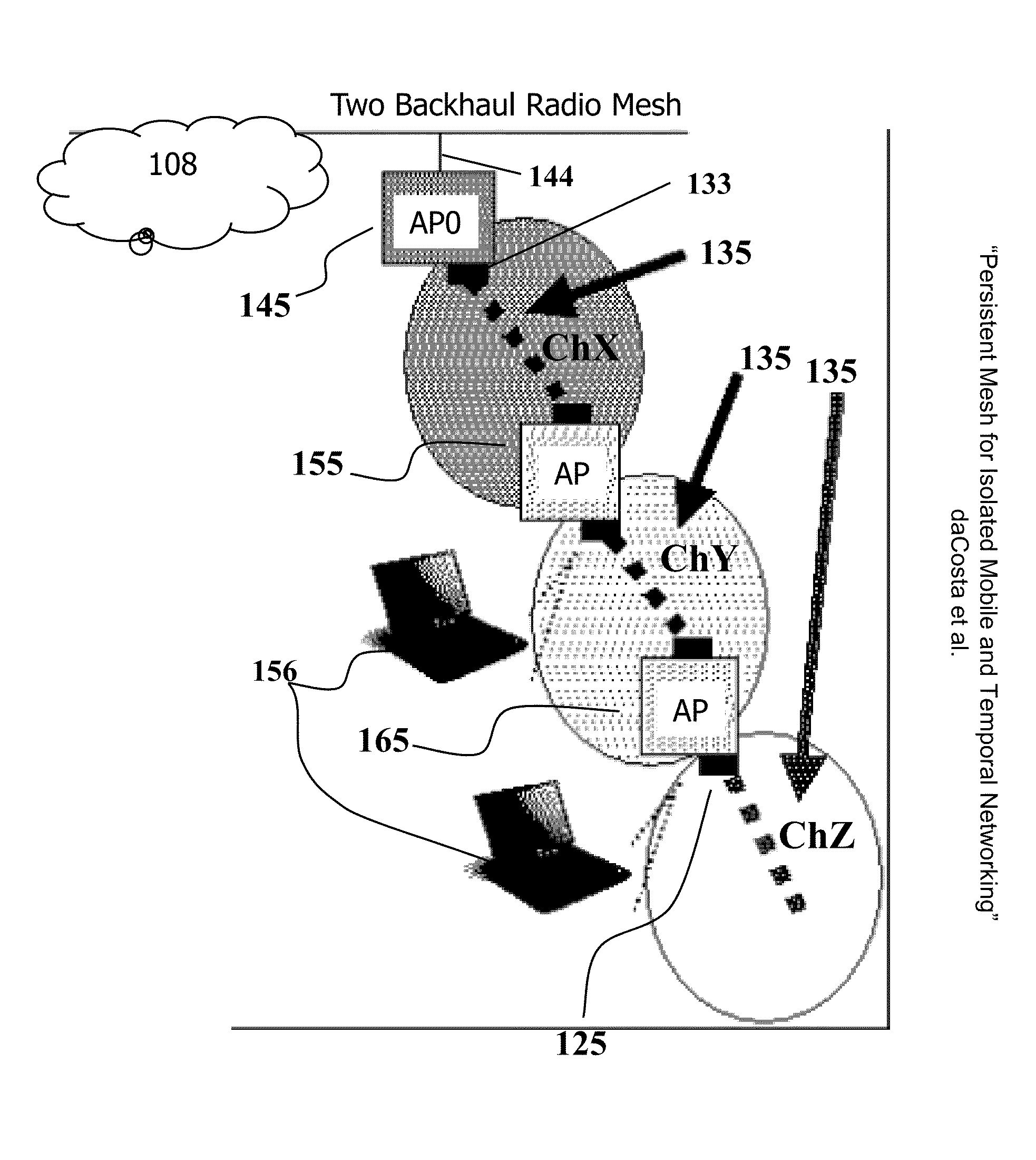
[0043]Depicted in FIG. 1(B) and in FIG. 2 are two examples of mesh networks featuring links to an external network. Turning first to FIG. 1(B), depicted there are three nodes 145, 155, 165, wherein each node comprises an uplink connection and a downlink connection. Each node is considered an access point or “AP,” and each node is physically identical, in one embodiment. For example, the top...


PUM


Abstract

A structured wireless mesh network is disclosed where a tree-like connection topology is formed. In one embodiment, each node has separate uplink and downlink radios operating on different channels. When a cluster of such nodes becomes isolated as in the case of a mobile mesh application, a node in the cluster according to this invention acts as a root node thus enabling the tree structure to persist, even in isolation. Example methods of joining sub networks are disclosed that guide the joining of mesh networks and channel management. Nodes that may operate in isolation also support a distributed DHCP capability such that IP addresses are assigned to clients even when a connection to a central DHCP server is unavailable.

Description

CROSS REFERENCE TO RELATED APPLICATIONS[0001]This application claims the benefit of claim priority as a continuation of U.S. application Ser. No. 12 / 696,947, filed on Jan. 29, 2010, presently pending which in turn claimed priority as a non-provisional filing of Ser. No. 61 / 148,803 filed on Jan. 30, 2009, presently expired, and also as a continuation in part of the U.S. Utility application Ser. No. 11 / 084,330 filed Mar. 17, 2005, currently abandoned which in turn is a continuation-in-part of U.S. Utility application Ser. No. 10 / 434,948, filed on May 8, 2003, patented as U.S. Pat. No. 7,420,952 on Sep. 2, 2008. Further, the Ser. No. 12 / 696,947 application claimed priority as a continuation in part of the U.S. Utility application Ser. No. 12 / 352,457, filed on Jan. 13, 2009, currently patented as U.S. Pat. No. 8,477,762 on Jun. 12, 2013.COPYRIGHT NOTICE[0002]A portion of the disclosure of this patent document contains material which is subject to copyright protection. The copyright owne...

Claims


Application Information

Patent Timeline
Patent Type & Authority Applications(United States)
IPC IPC(8): H04W84/10H04L45/02
CPCH04W84/10H04W40/32H04W84/22H04W88/04H04W40/246H04W84/02H04L12/66H04L45/04H04W84/005H04W84/20H04L45/02H04L12/46H04W84/18H04L12/2858H04W40/248H04W92/04H04W92/045H04L41/12H04W40/24H04W8/005
Inventor DACOSTA, FRANCISDAYANANDAN, SRIRAM
Owner DYNAMIC MESH NETWORKS
Learn More