
Mouthpiece

a mouthpiece and mouth technology, applied in the field of mouthpieces, can solve the problems of short time for ending the vaporization of nicotine from tobacco leaves, harming the flavor,

Inactive Publication Date: 2013-12-19
SHIMIZU KAZUHIKO
View PDF1 Cites 30 Cited by
  • Summary
  • Abstract
  • Description
  • Claims
  • Application Information

AI Technical Summary

Benefits of technology

This patent describes a new mouthpiece for a non-combustion smoking tool that helps to control the flow of air when a smoker inhales through the mouthpiece. This new mouthpiece has a unique structure that prevents the filter from absorbing too much of the nicotine vapor, allowing the smoker to inhale most of the nicotine in a more desirable concentration. The mouthpiece can also be combined with a cigarette guide tube for easy use with the non-combustion smoking tool. Additionally, the mouthpiece is designed to be easily removed from the non-combustion smoking tool with the inserted filter cigarette. Overall, this new mouthpiece provides a better user experience for smoking non-combustion cigarettes.

Problems solved by technology

When the tool of the earlier application of the present application and the non-combustion smoking tool proposed in Patent Document 3 were actually used by inserting a filter cigarette therein, the following problems were found.
However, when inhaled through the filter similarly as when normally smoking by lighting them, most of the nicotine vaporized out of the tobacco leaves by heating the tobacco leaves is absorbed by the filter, so that a smoker can inhale only a small amount of nicotine vaporized out of the tobacco leaves.
However, when heated at such a high temperature, the tobacco leaves get burned to add burning smell, thereby not only harming the flavor, but also ending the vaporization of nicotine from the tobacco leaves in a short time.

Method used


Image

  • Mouthpiece
  • Mouthpiece
  • Mouthpiece

Examples


example 1

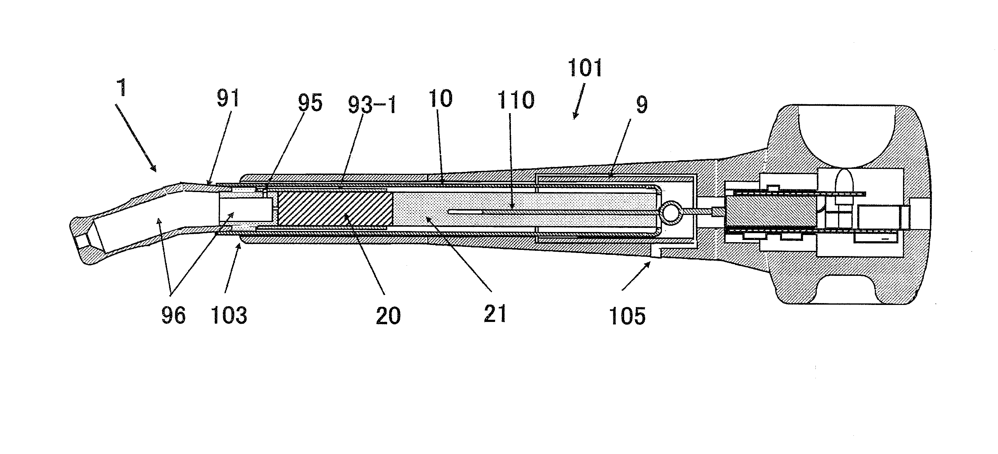
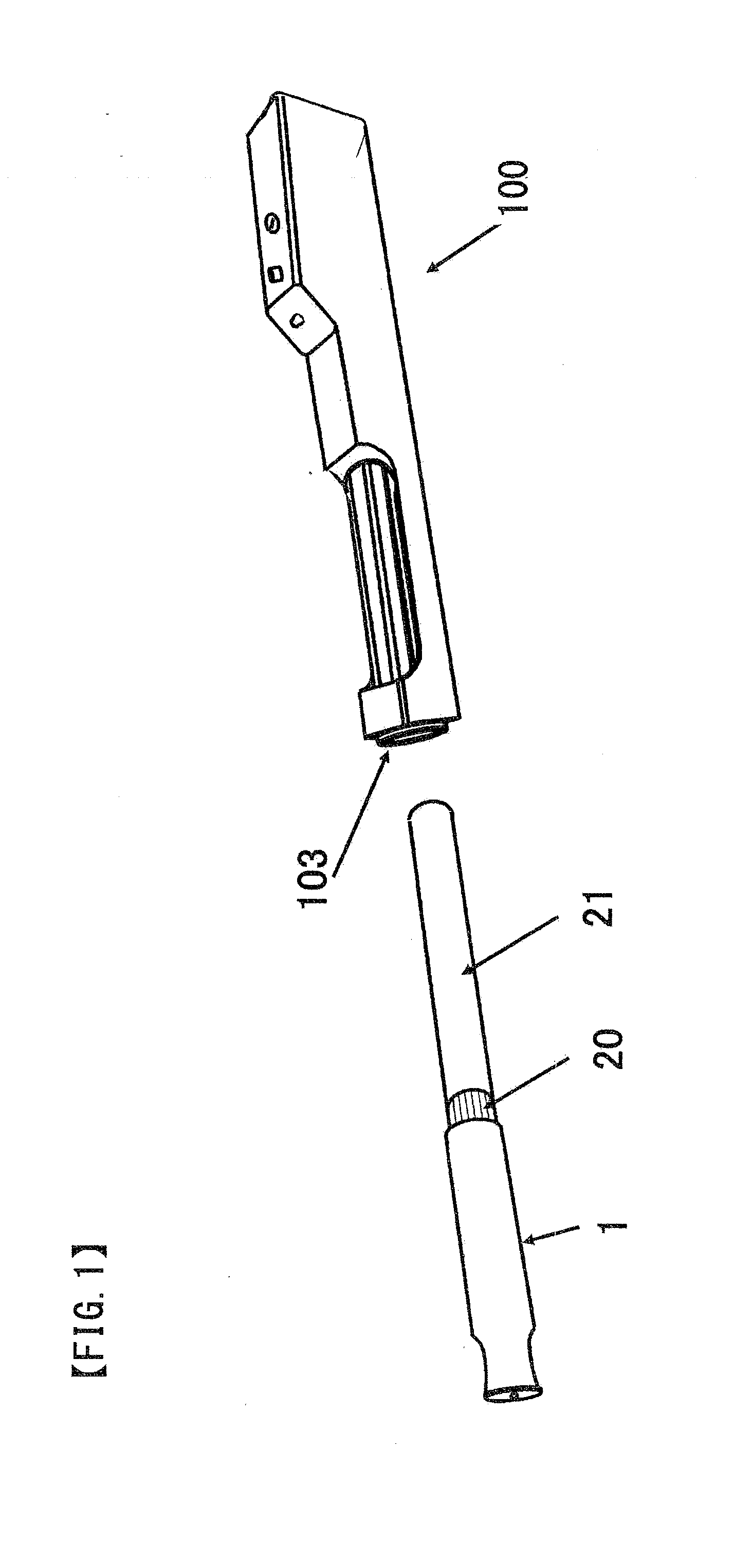
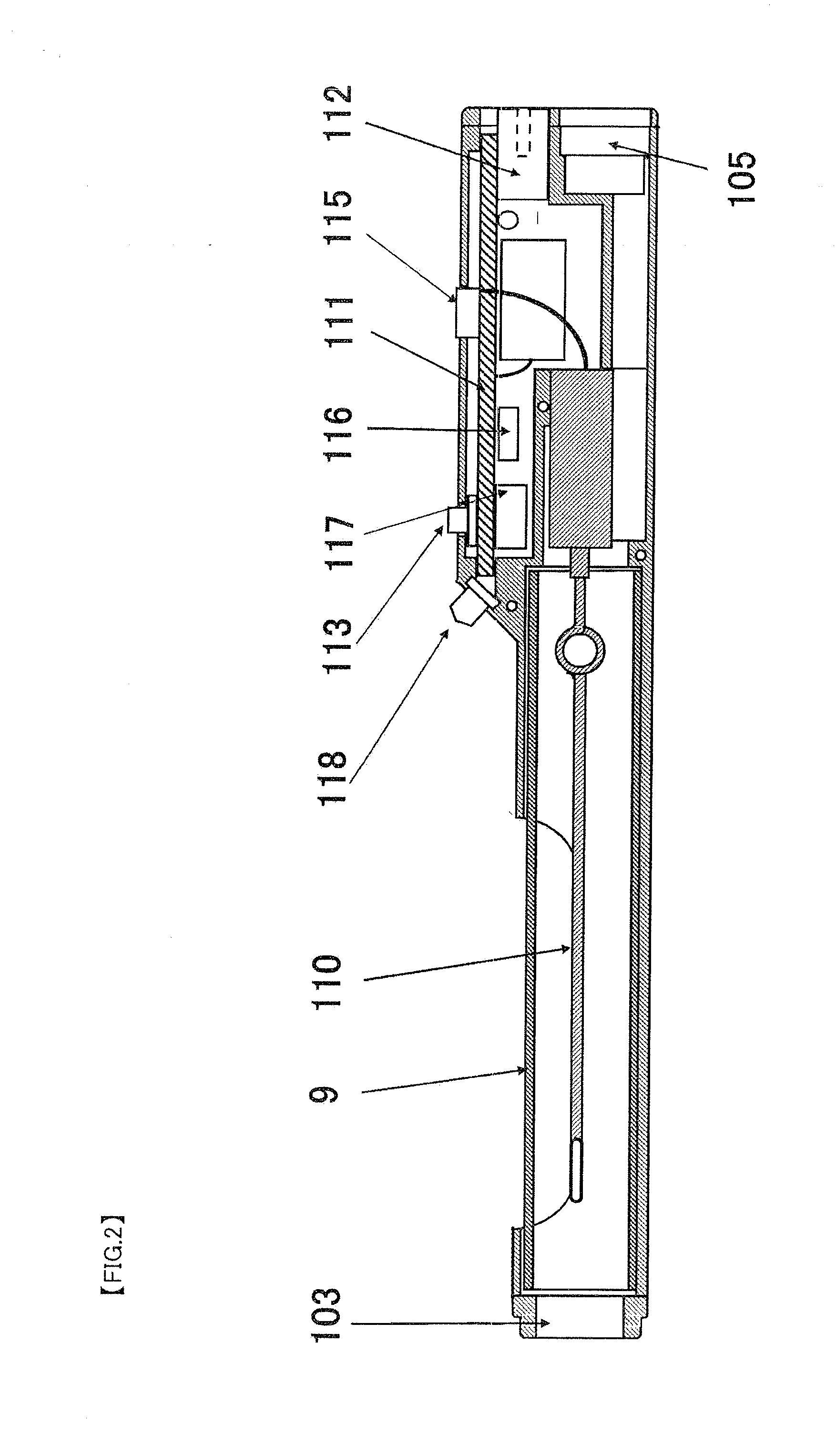
[0052]FIG. 3 shows a cross-sectional view of a mouthpiece of EXAMPLE 1 of the present application. The mouthpiece 1 comprises an inhalation inlet 2, an air flow control element 3 and a filter housing part 4. As shown in FIG. 4, the air flow control element 3 comprises a combination of two components 31 and 34. The outer diameter of the component 31 is designed to be substantially the same as the inner diameter of the filter housing part 4. The outer diameter of the component 34 is designed to be substantially equal to or smaller than the outer diameter of the component 31, and equal to or larger than the diameter of an axial hole 32. The mouthpiece 1 has an outer diameter designed to tightly fit an insertion opening 103 of the non-combustion smoking tool shown in FIGS. 1 and 2 so as to prevent air leakage.

[0053]FIG. 5 shows an appearance view of another example of an air control component 3. This air control component 3 has a shape similar to a normal gear, and comprises six gear te...

example 2

[0062]FIG. 7 shows an appearance view of a mouthpiece of EXAMPLE 2 of the present application. FIG. 8 is an A-A′ cross-sectional view of FIG. 7. This mouthpiece comprises a mouthpiece outer case, an air flow control element 3-1 and a filter housing part 4.

[0063]As shown in FIG. 7 and FIG. 8, the mouthpiece 1 has two slits 6. The slits 6 serve to guide produced nicotine to the inhalation inlet 2, and facilitate insertion into the non-combustion smoking tool or facilitate insertion of a cigarette guide tube 10 by allowing the outer diameter of the mouthpiece 1 to be virtually reduced when the mouthpiece 1 is pressed from outside upon insertion into the non-combustion smoking tool or upon insertion of the cigarette guide tube 10 into the mouthpiece 1 as described later. Although FIG. 7 describes the case of two, the same effect can be obtained with three or more.

[0064]Further, the slits have length L1 which is designed to be longer than insertion length L2 of the filter cigarette in th...

example 3

[0072]FIG. 11 is an appearance view of a novel mouthpiece 1 of EXAMPLE 3 of the present application. FIG. 12 is a right side view of FIG. 11. This mouthpiece is an embodiment of the subject matter of the present invention based on the structure of the mouthpiece instead of the air flow control element. The mouthpiece 1 comprises four parts, in which 93 is a filter housing part, and has a portion to fit a part 92 as shown in a cross-sectional view of FIG. 13. This portion is rotated by a smoker for use so that a groove 94 is rotated to match one of holes 95-1, 2, 3. A hole 97 is formed in a central wall of the filter housing part 93. As shown in the cross-sectional view of FIG. 13, the part 92 is designed to fit a part 91 as well, and has the holes 95-1, 2, 3. A right side of the part 92 is a cover which has two holes 99 of different sizes. When the part 93 is rotated to allow the groove 94 to match the hole 95-1, a hole 99 with a diameter substantially equal to the hole 97 is positi...


PUM


Abstract

A non-combustion smoking tool, which uses a real filter cigarette as it is, and which vaporizes nicotine from the tobacco leaves without lighting the product to enable inhalation of the vaporized nicotine, has a problem that a smoker cannot take in 100% of the vaporized nicotine. Thus, a mouthpiece is designed to have an air flow control structure or an air flow control element, or to be combined with a cigarette guide tube, so as to enable the mouthpiece to vary the rate at which the nicotine vaporized from the tobacco leaves is taken in.

Description

TECHNICAL FIELD[0001]The present invention relates to a mouthpiece provided for non-combustion smoking tools and used in combination with a non-combustion smoking tool of Japanese Patent Application 2009-049879 or Japanese Patent Application 2009-293338 made by the present applicant (each hereinafter referred to as “tool—of the earlier application of the present application”), a non-combustion cigarette system disclosed in Japanese Translation of PCT Application 2009-509521 or a pipe-type non-combustion smoking tool.BACKGROUND ART[0002]The “tool of the earlier application of the present application” and the non-combustion smoking tools disclosed in Patent Document 3and Patent Document 4 have been proposed to improve various problems of a normal smoking method to light tobacco leaves for smoking, and are tools which, while using a generally commercially available cigarette or cigar as it is, can vaporize nicotine from the tobacco leaves at a suitable temperature to enable inhalation ...

Claims


Application Information

Patent Timeline
Patent Type & Authority Applications(United States)
IPC IPC(8): A24F7/02A24F40/20A24F40/485A24F40/50
CPCA24F7/02A24F13/02A24F40/50A24F40/485A24F40/20
Inventor SHIMIZU, KAZUHIKO
Owner SHIMIZU KAZUHIKO
Learn More