
Combined high energy igniter and flame detector

a high-energy igniter and flame detector technology, applied in the direction of burner control devices, combustion regulation, burners, etc., can solve the problems of short window for ignition and detection, ignition problems,

Active Publication Date: 2013-12-12
CHENTRONICS
View PDF7 Cites 9 Cited by
  • Summary
  • Abstract
  • Description
  • Claims
  • Application Information

AI Technical Summary

Benefits of technology

The present invention provides a pilot burner that can simultaneously generate a spark and conduct electricity. The pilot burner has a source of electrical energy, a spark rod, and a housing with a fuel flow passage. The spark rod connects to the source of electrical energy and the housing contains a flame detection circuit. The pilot burner can generate a flame by igniting fuel with a spark and detecting the flame using the flame detection circuit. The invention also provides an apparatus for ignition and flame detection, an ignition device, and a process for simultaneous ignition and flame detection. The technical effects of the invention include improved ignition and flame detection capabilities in high energy igniters.

Problems solved by technology

While this type of ignition can be low cost, it can be inconsistent when ignition conditions are not ideal.
Moisture from steam or rain, contamination and heavy fuel can all generate ignition problems when using an HT system.
The window for ignition and detection is therefore very short.

Method used


Image

  • Combined high energy igniter and flame detector
  • Combined high energy igniter and flame detector
  • Combined high energy igniter and flame detector

Examples


Embodiment Construction

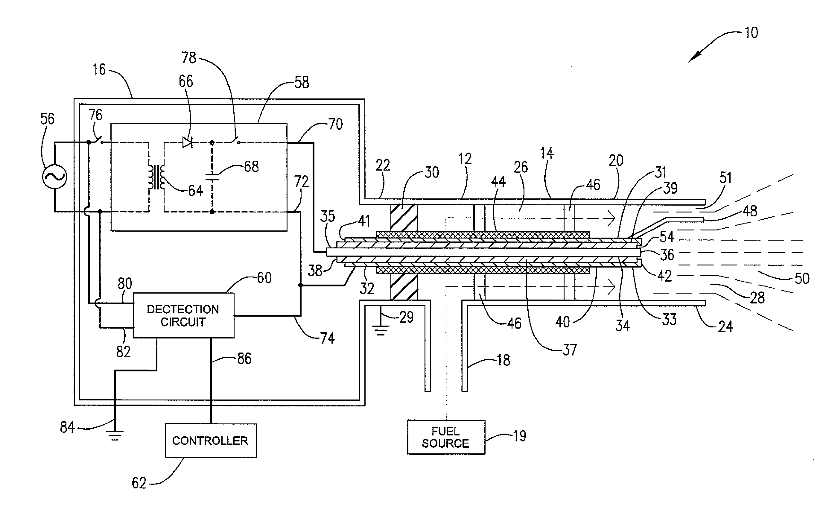
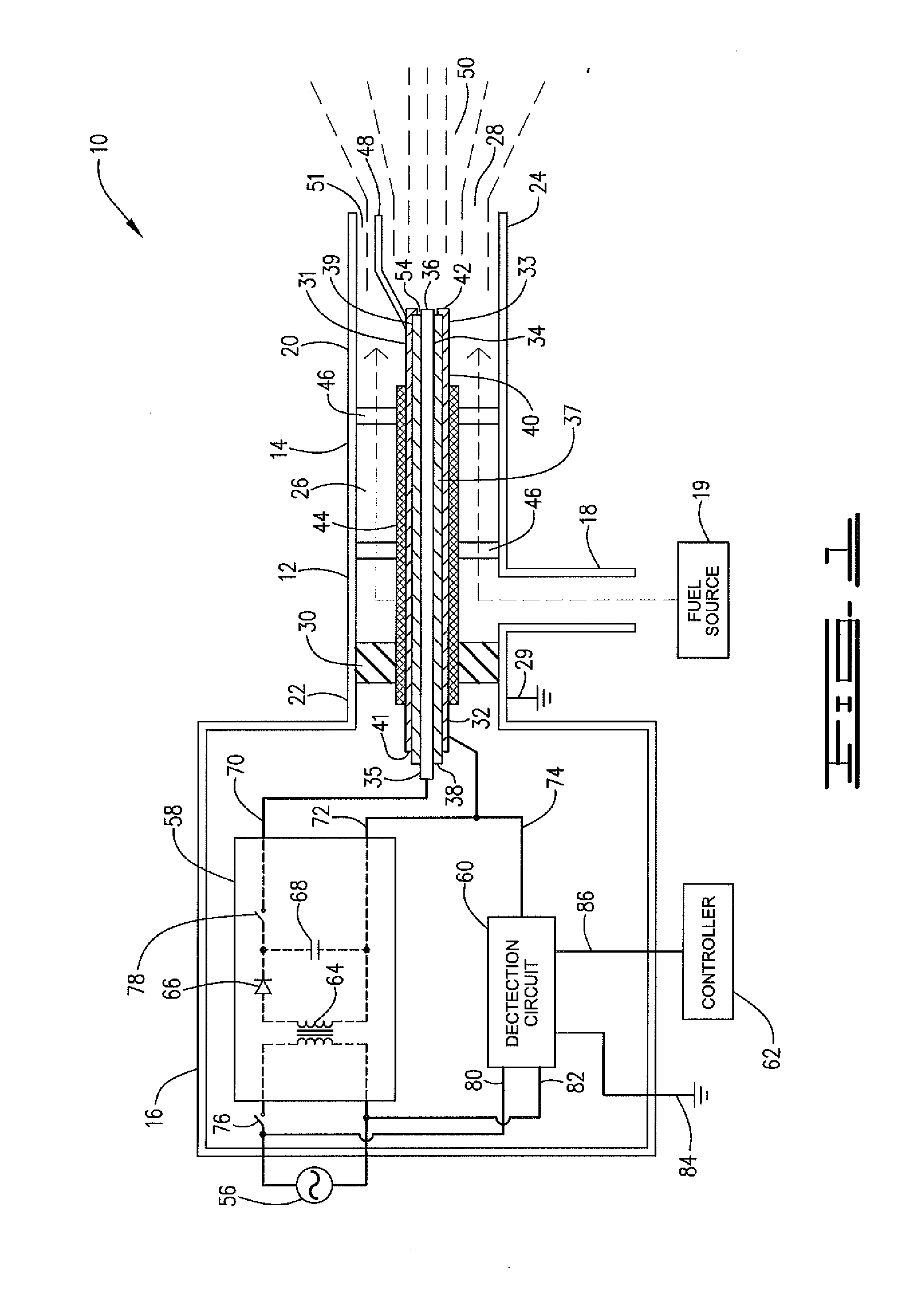
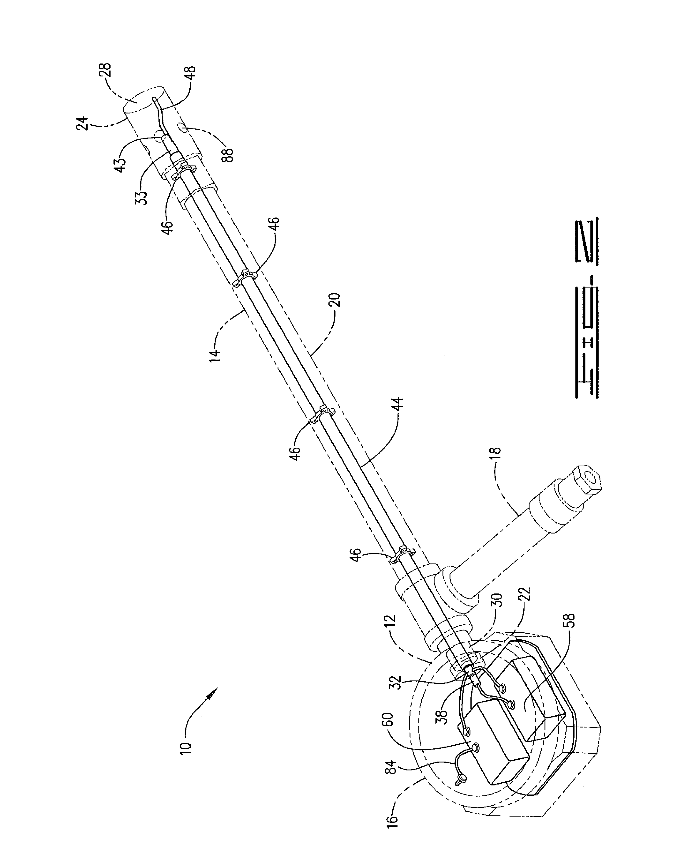
[0027]The description below and the figures illustrate a pilot burner or ignition system of the type used in a furnace having a main burner that supplies a fuel and air mixture to the furnace and a pilot burner adjacent to the main burner for igniting the fuel and air mixture. While the invention is described in the context of a pilot burner for such a furnace, it will be appreciated that the inventive ignition device is more broadly applicable as an ignition and flame detection system for fuels.

[0028]Referring now to FIGS. 1 through 4, an ignition device or pilot burner 10 in accordance with one embodiment of the invention is illustrated. Pilot burner 10 has a housing 12. Housing 12 is comprised of a main pipe or tube portion 14, electronics enclosure 16 and fuel introduction pipe 18. Tube portion 14 has a wall 20 having a first end 22 and a second end 24 and a longitudinal fuel flow passage or fuel channel 26 defined by wall 20. First end 22 is connected to electronics enclosure 1...


PUM


Abstract

An apparatus and method are provided for improved gas pilot burners, which are capable of simultaneous flame ignition and flame detection. More particularly, the invention provides for an apparatus and method capable of simultaneous high-energy ignition and flame ionization detection in a high-energy igniter that utilizes a spark rod located in a fuel channel.

Description

BACKGROUND[0001]1. Field of the Invention[0002]This invention pertains to ignition and sensing systems and more particularly to flame ignition and flame detecting or sensing systems. Even more particularly, the invention pertains to such systems having a spark type ignition.[0003]2. Description of the Related Art[0004]A gas pilot burner is a device used to create a stable pilot flame by combustion of a low flow rate (relative to the main burner) gaseous fuel-air mixture. The pilot flame is used to light a larger main burner, or a difficult to light fuel. Gas pilot designs normally include an ignition system and a flame detection system. The two most common types of ignition systems used in gas pilot burners are high tension (HT) and high-energy ignition (HEI). Flame detection is typically by a flame ionization detection (FID) system.[0005]An HT flame ignition system typically utilizes a high voltage source and an HT spark plug or spark rod. The high voltage source provides high volt...

Claims


Application Information

Patent Timeline
IPC IPC(8): F23Q9/14F23N5/24F23Q3/00
CPCF23D2207/00F23D2208/10F23Q3/008F23N5/123F23N2229/02F23N2227/22F23N2227/36F23N5/24F23Q3/00F23Q9/14
Inventor STRONG, ANDREW H.
Owner CHENTRONICS
Learn More