
Magnifying glass with lighting function

a technology of magnification glass and function, applied in the field of magnification glass with a lighting function, can solve the problems of inconvenient use of magnifying glass, high precision of precision instruments, and inability to uniformly illuminate the surface p of objects, so as to increase production costs, increase visibility, and prevent viewer from erroneous operation or eye fatigue

Inactive Publication Date: 2013-12-12
HUANG KUAN DI +1
View PDF1 Cites 3 Cited by
  • Summary
  • Abstract
  • Description
  • Claims
  • Application Information

AI Technical Summary

Benefits of technology

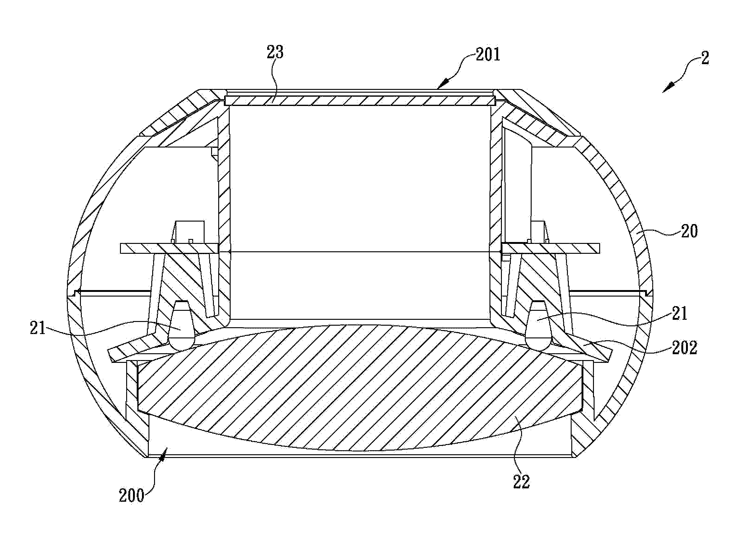
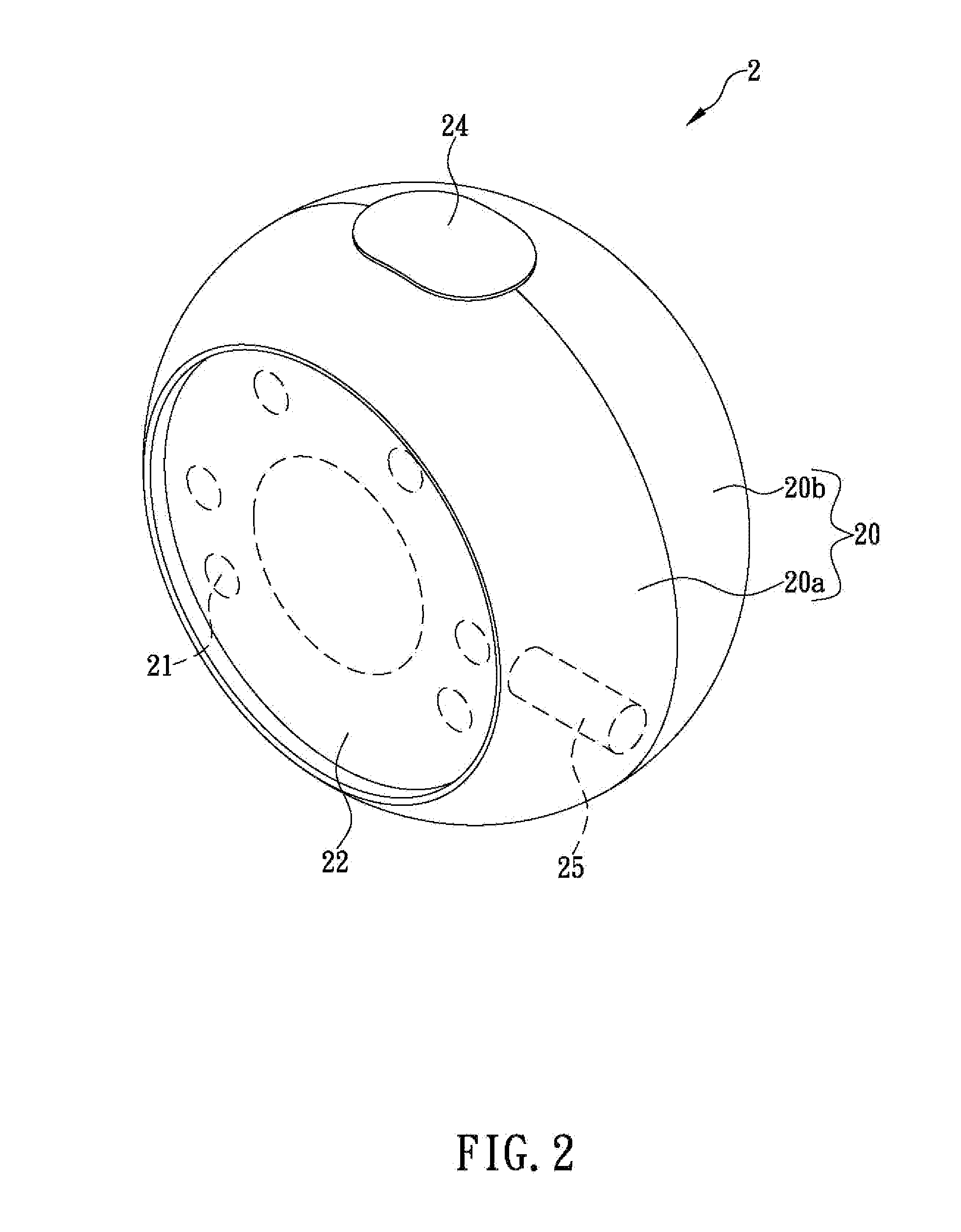
The present invention is a magnifying glass with a lighting function. It includes a housing, a plurality of light-emitting elements, and a convex lens. The light-emitting elements are fixed to the housing and emit visible light outward of the objective aperture. The convex lens is fixed to the housing and is in front of the light-emitting elements. The visible light emitted by the light-emitting elements is refracted by the convex lens and then projected diffusely onto the surface of an object to form a light projected area on the object, which illuminates the object uniformly. The overlapping light projected areas prevent non-uniform illumination and protect the viewer from eye fatigue and keep them from erroneous operation. The magnifying glass further includes a light-permeable plate fixed to the housing to protect the inner side of the convex lens from grime that may enter the housing.

Problems solved by technology

These precision instruments require highly precise operation, for maintenance for example, in which the components of the instruments are usually unidentifiable with the naked eye and must be handled with the assistance of auxiliary tools.
However, as an ordinary magnifying glass cannot light up the object being viewed, a lack of light will hinder the viewer from clearly seeing the details of the object and consequently from performing the intended work, which makes the magnifying glass undesirable in practical use.
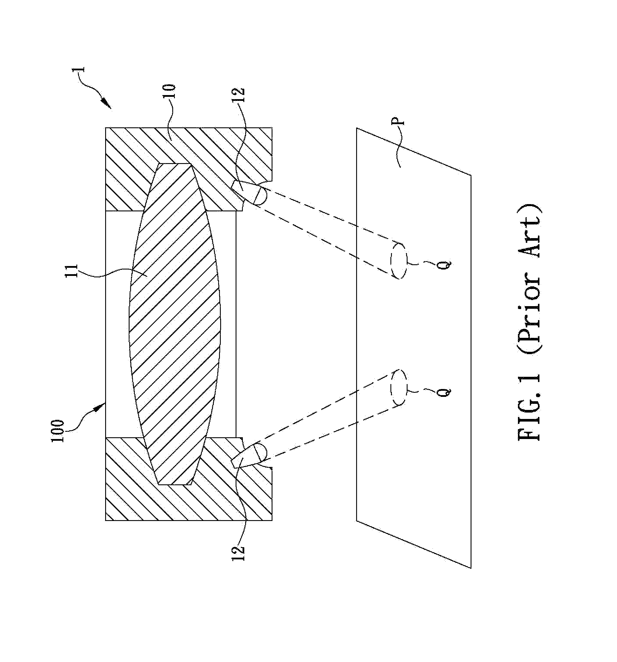
Consequently, the surface P of the object is not uniformly illuminated, and the lighting effect in general leaves much to be desired.
Now that the viewer can only see the few illuminated areas on the surface P of the object through the convex lens 11, the visibility of the object is poor, meaning the details of the object cannot be seen in full.
Hence, not only is erroneous operation prone to happen, but also the viewer's eyes tend to fatigue after long-term use of the magnifying glass 1.

Method used


Image

  • Magnifying glass with lighting function
  • Magnifying glass with lighting function
  • Magnifying glass with lighting function

Examples


Embodiment Construction

[0016]The inventor of the present invention has long been engaged in the research and development of magnifying glasses and like optical instruments. In the process, the inventor has found that the existing magnifying glasses with light-emitting elements can only light up some areas of the object being viewed while leaving other areas unilluminated. Based on the inventor's observation, the cause of this non-uniform illumination is that the light-emitting elements of a conventional magnifying glass can only project small light spots on the surface of the object being viewed. Since the light is not shone over the surface of the object in a diffused manner, the viewer does not receive full assistance from the lighting of the light-emitting elements, and the viewer's eyes may fatigue as a result. While attempts have been made to improve the conventional magnifying glasses, with a view to overcoming the aforesaid problems, an ideal solution has yet to be found. In consideration of this, ...


PUM


Abstract

The present invention is to provide a magnifying glass with a lighting function, which includes a housing having a front side formed with an objective aperture, a rear side formed with a viewing aperture which is opposite to and in communication with the objective aperture, and a fixing portion provided therein and facing the objective aperture; a plurality of light-emitting elements fixed to the fixing portion and able to emit visible light outward of the objective aperture; and a convex lens fixed to the housing at a position corresponding to the objective aperture and in front of the light-emitting elements. Thus, the visible light emitted by each light-emitting element is refracted by the convex lens and then projected onto the surface of an object to form a light projected area on the object, wherein the light projected areas overlap with one another to illuminate the surface of the object uniformly.

Description

FIELD OF THE INVENTION[0001]The present invention relates to a magnifying glass with a lighting function, more particularly to a magnifying glass including a housing having a front side formed with an objective aperture, a plurality of light-emitting elements capable of emitting visible light outward of the objective aperture, and a convex lens fixed to the housing at a position corresponding to the objective aperture and in front of the light-emitting element, such that the visible light emitted by each light-emitting element is refracted by the convex lens and then projected onto the surface of an object to form a light projected area on the object, and the light projected areas overlap with one another to illuminate the surface of the object uniformly.BACKGROUND OF THE INVENTION[0002]With the development of electronic technology, precision instruments of all kinds have been continuously improved. These precision instruments require highly precise operation, for maintenance for ex...

Claims


Application Information

Patent Timeline
IPC IPC(8): G02B25/02
CPCG02B25/02
Inventor HUANG, KUAN-DI
Owner HUANG KUAN DI
Learn More