Magnetic tape recording in data format using an efficient reverse concatenated modulation code

a reverse concatenation and data format technology, applied in the field of magnetic tape data storage format, can solve the problems of inability to perform soft detection using current data structures, inability to use soft detection with current data format architecture, and inability to insert modulation codes

Inactive Publication Date: 2013-12-05
BEIJING PIANRUOJINGHONG TECH CO LTD
View PDF5 Cites 15 Cited by
  • Summary
  • Abstract
  • Description
  • Claims
  • Application Information

AI Technical Summary

Problems solved by technology

The problem with this architecture is that the modulation code is inserted between the error correction codes (ECCs) and the data as it is written on the magnetic tape.
These data detectors are referred to as ‘soft detectors.’ It is not possible to perform soft detection using current data structures.
Thus, soft detectors cannot be used with the current data format architecture.

Method used

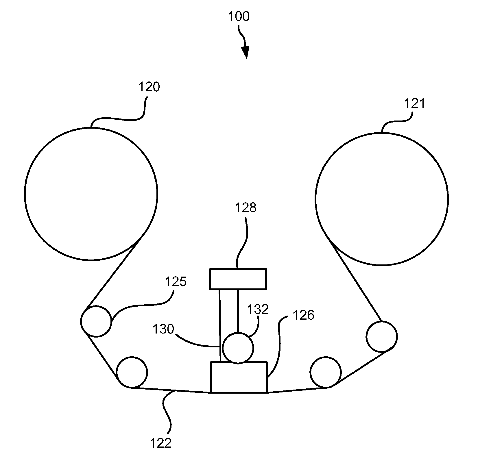
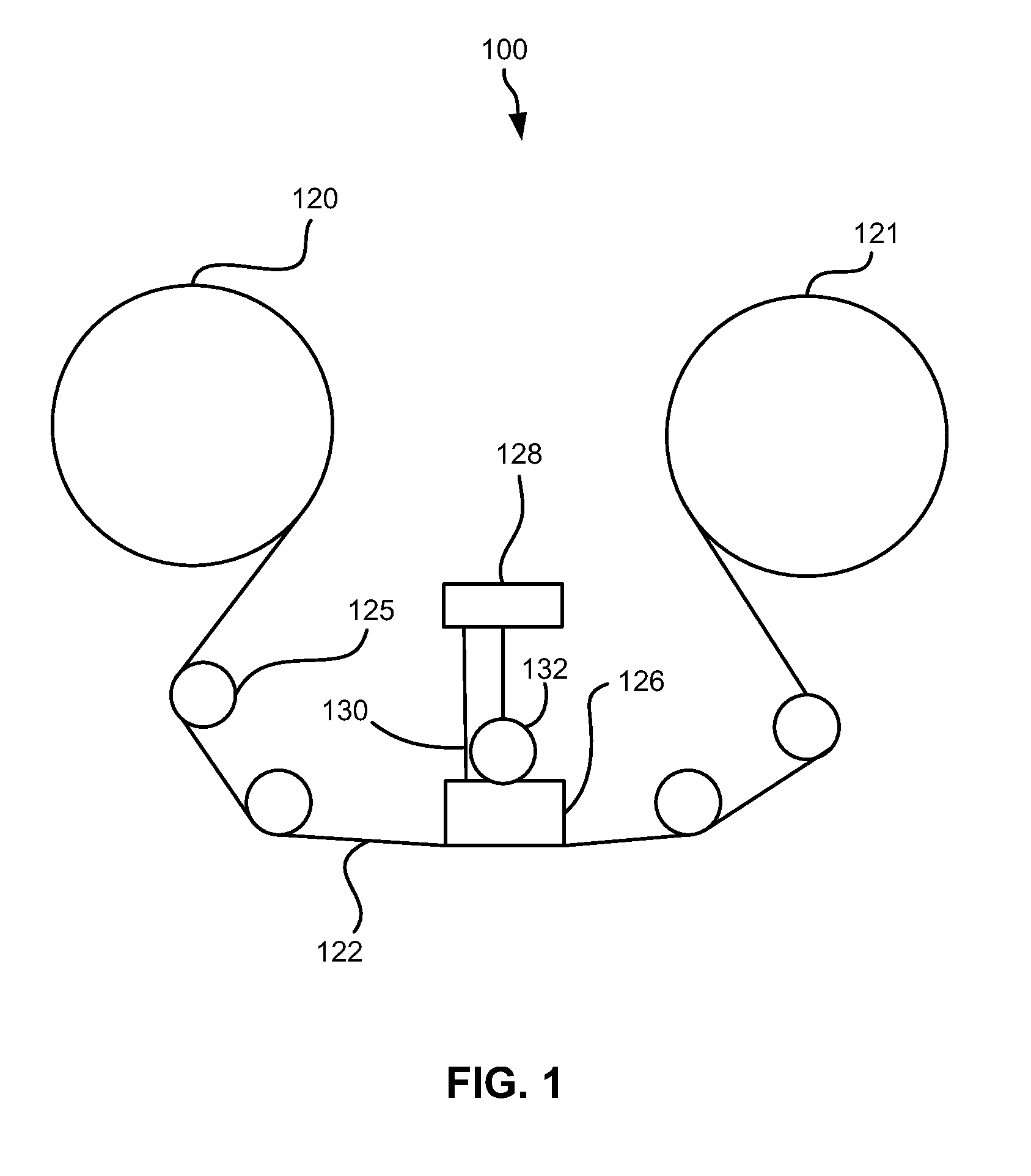
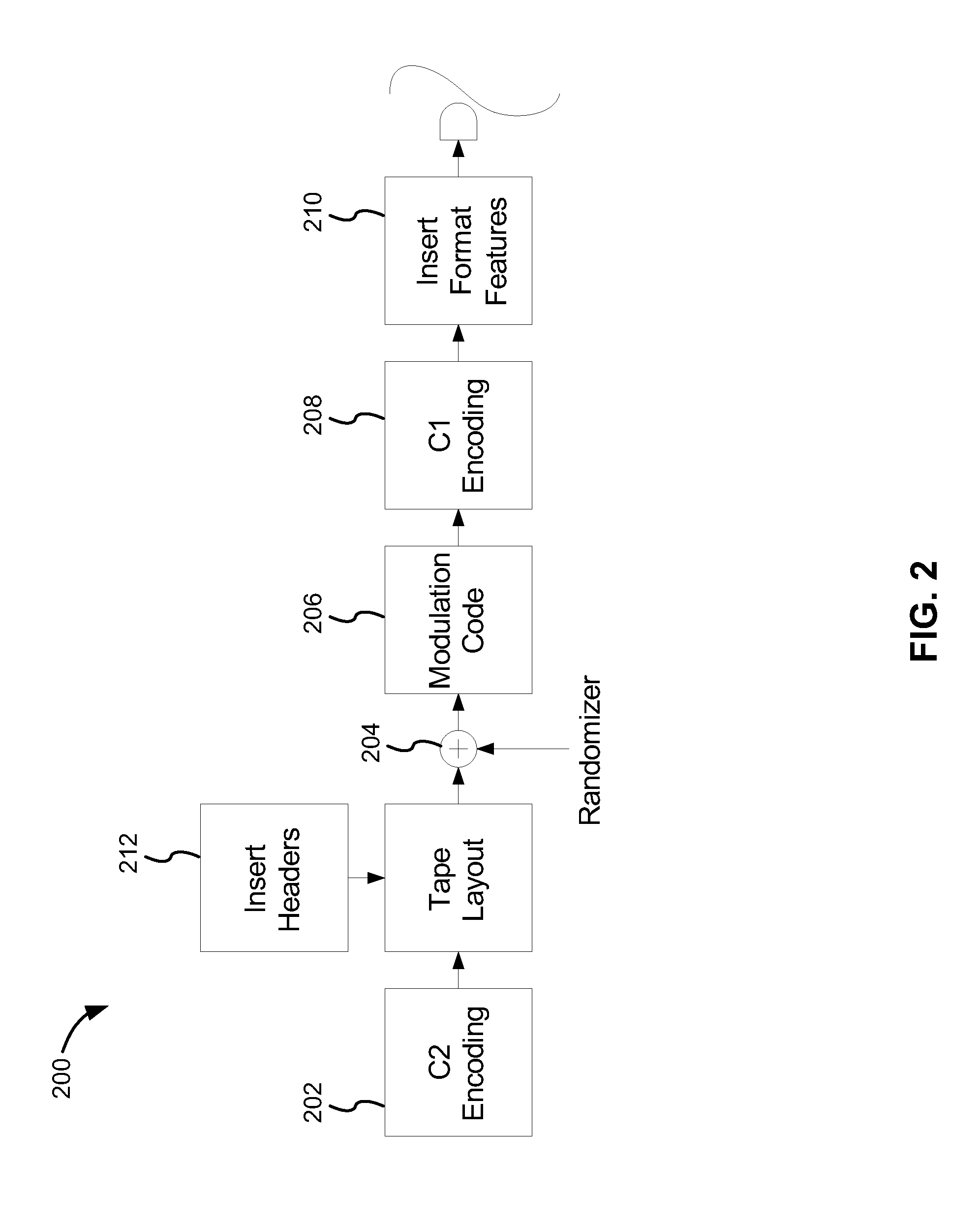

Image

  • Magnetic tape recording in data format using an efficient reverse concatenated modulation code
  • Magnetic tape recording in data format using an efficient reverse concatenated modulation code
  • Magnetic tape recording in data format using an efficient reverse concatenated modulation code

Examples


example h -

Example H-Matrix

[0071]The example H-matrix may be represented by the connectivity matrix shown below, according to one embodiment. In this connectivity matrix, each check node is listed in the left column starting with index 0 (the top row of the H-matrix). The location of each 1 entry within the check node of the H-matrix is given in the corresponding row of the connectivity matrix, again starting with bit index 0 being the left column.

Check-Node #Symbol-Node Indices025671014112389103156940271053481160346757101181289

Simple Example of a Check-Node Connectivity Matrix

[0072]The systematic H-Matrix for a LDPC code, according to one embodiment, may have 120 check-nodes (M=120) and 1992 symbol nodes (N=1992). This creates 120 parity bits which normally may be concatenated to the end of the modulation-encoded block. However, since the data has been modulation encoded, this is not acceptable. Having 120 parity bits at the end of the 1872 bit modulation-encoded block would destroy the prope...


PUM

PropertyMeasurementUnit
magneticaaaaaaaaaa
sizeaaaaaaaaaa
lengthaaaaaaaaaa

Abstract

In one embodiment, a method for writing data to a magnetic tape utilizing a rate-(232 / 234) reverse concatenated modulation code includes receiving a data stream comprising one or more data sets, separating each data set into a plurality of sub data sets, encoding each sub data set with a C2 encoding, encoding each C2-encoded sub data set with the modulation code, encoding each modulated sub data set with a C1 encoding, and simultaneously writing the encoded modulated sub data sets to data tracks of the magnetic tape. Other methods for writing data to a magnetic tape utilizing a rate-(232 / 234) reverse concatenated modulation code are described according to various other embodiments.

Description

RELATED APPLICATIONS[0001]The present application is a continuation of copending U.S. patent application Ser. No. 13 / 483,004, filed May 29, 2012; which is herein incorporated by reference.[0002]Furthermore, the present application is related to U.S. patent application Ser. No. 13 / 483,015, entitled “Partial Reverse Concatenation for Data Storage Devices Using Composite Codes” to Roy Cideciyan et al. filed May 29, 2012; and to U.S. patent application Ser. No. 13 / 483,026 entitled “Methods for Partial Reverse Concatenation for Data Storage Devices Using Composite Codes” to Roy Cideciyan et al., filed May 29, 2012, which are herein incorporated by reference.BACKGROUND[0003]The present invention relates to a magnetic tape data storage format, and more particularly, to storing data on a magnetic tape using a reverse concatenated modulation code with a low-density parity check (LDPC) code.[0004]It has been projected that the capacity of magnetic tape cartridges will double every two years w...

Claims


Application Information

Patent Timeline
Patent Type & Authority Applications(United States)
IPC IPC(8): G11B5/008H03M13/13
CPCG11B5/00813H03M13/13G11B20/1833G11B2020/1836G11B2020/185G11B2020/1853G11B2220/90H03M5/145H03M13/1102H03M13/1515H03M13/2906
Inventor CIDECIYAN, ROY D.HUTCHINS, ROBERT A.MITTLEHOLZER, THOMASOELCER, SEDAT
Owner BEIJING PIANRUOJINGHONG TECH CO LTD
Why Eureka
Try Eureka