
Beamformer configurable for connecting a variable number of antennas and radio circuits

Inactive Publication Date: 2013-12-05
MAGNOLIA BROADLAND INC
View PDF5 Cites 51 Cited by
  • Summary
  • Abstract
  • Description
  • Claims
  • Application Information

AI Technical Summary

Benefits of technology

This patent is about a new way to route signals in a wireless network that helps reduce signal loss. It uses a special circuit called an RF routing module that is designed to work well with multiple antennas and channels. This module helps to make the network more efficient and reliable.

Problems solved by technology

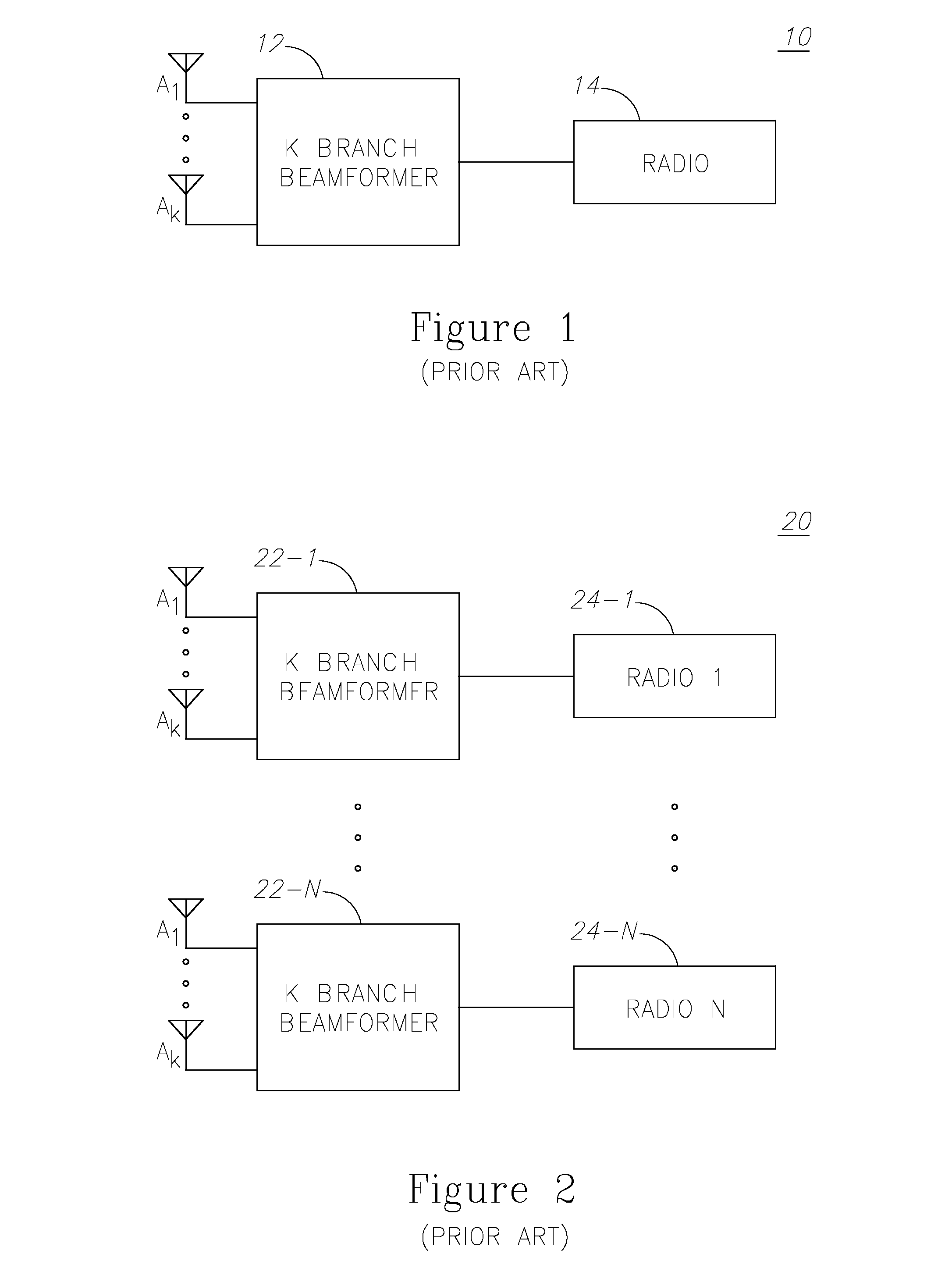
This is achieved by combining elements in the array in such a way that signals at particular angles experience constructive interference while others experience destructive interference.
ASIC design however usually requires preliminary interface definition, and once done, flexibility to interfaces modifications is limited.
While K inputs is the maximum, one may use only part of the inputs (for instance, when the implementation provides lower number of inputs); that however comes at the price of combining losses, generated by imbalanced inputs or lack of some of them.

Method used


Image

  • Beamformer configurable for connecting a variable number of antennas and radio circuits
  • Beamformer configurable for connecting a variable number of antennas and radio circuits
  • Beamformer configurable for connecting a variable number of antennas and radio circuits

Examples


Embodiment Construction

[0026]With specific reference now to the drawings in detail, it is stressed that the particulars shown are for the purpose of example and solely for discussing the preferred embodiments of the present invention, and are presented in the cause of providing what is believed to be the most useful and readily understood description of the principles and conceptual aspects of the invention. In this regard, no attempt is made to show structural details of the invention in more detail than is necessary for a fundamental understanding of the invention. The description taken with the drawings makes apparent to those skilled in the art how the several forms of the invention may be embodied in practice.

[0027]Before explaining the embodiments of the invention in detail, it is to be understood that the invention is not limited in its application to the details of construction and the arrangement of the components set forth in the following descriptions or illustrated in the drawings. The inventi...


PUM


Abstract

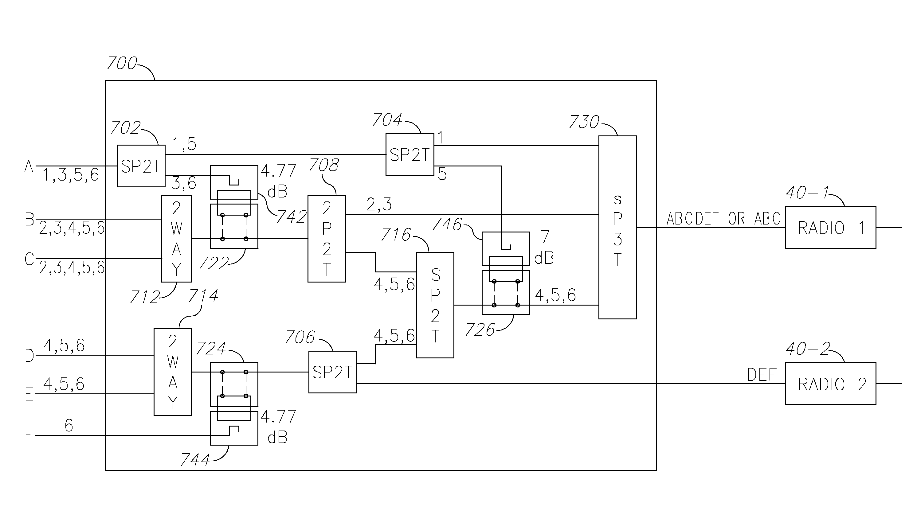
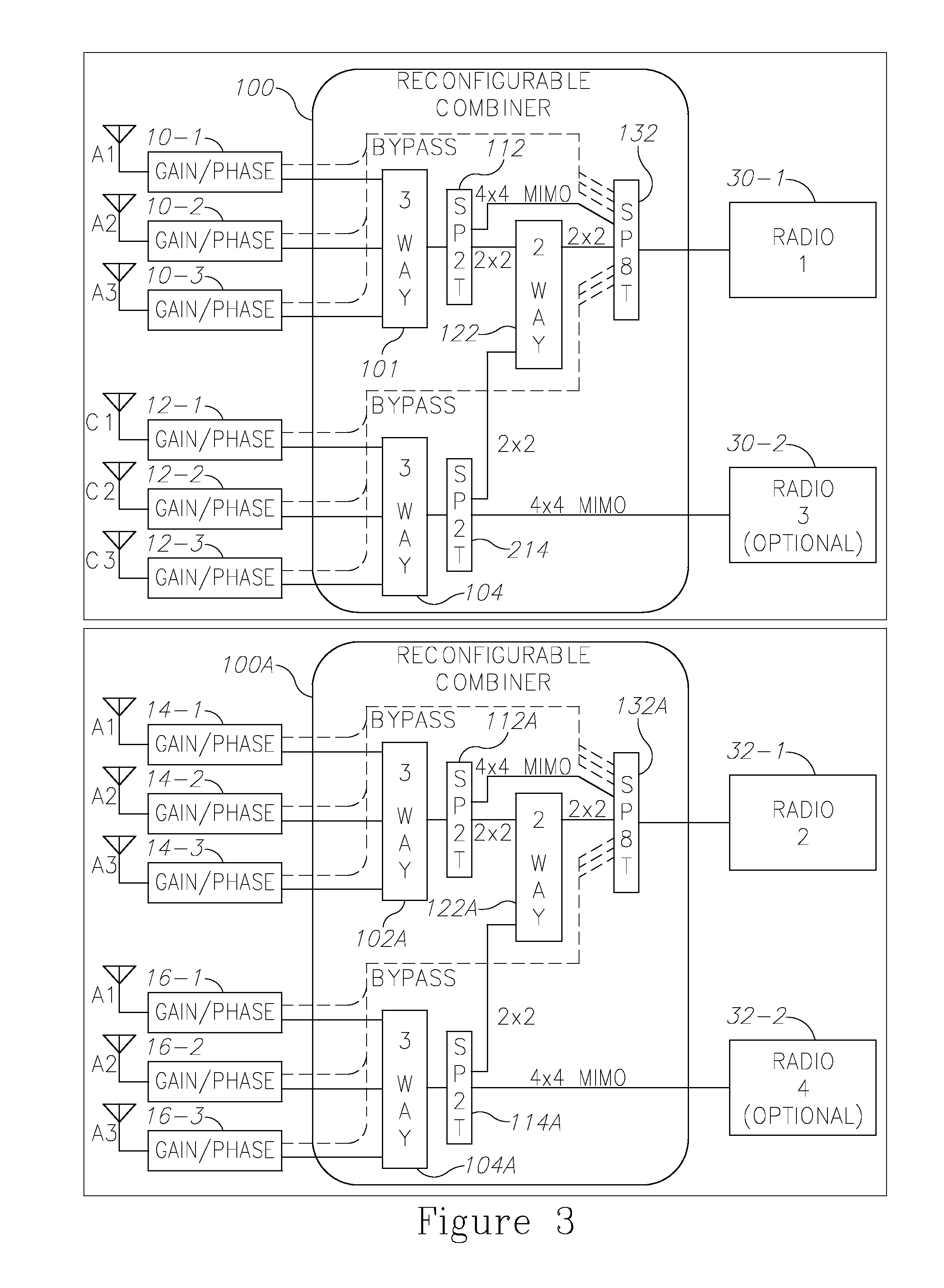
A reconfigurable RF routing module may include M RF inputs and N RF outputs, wherein M is greater than N; a plurality of RF switches arranged to select between incoming RF signals; a plurality of RF combiners arranged to combine RF signals to a single RF signal; and a plurality of RF couplers, each associated with a transfer switch and a specified attenuation, wherein the specified attenuation of each one of the plurality of RF couplers is selected so that the RF inputs of each one of the plurality of the RF combiners are combined in a balanced manner, wherein the switches, the combiners, and the RF couplers are configured to route any of 1 to M of the inputs into each of the N outputs.

Description

CROSS-REFERENCE TO RELATED APPLICATIONS[0001]This application is a continuation-in-part application of U.S. non-provisional patent application No. 13 / 630,146 filed on Sep. 28, 2012, which in turn claims benefit from U.S. provisional patent applications: 61 / 652,743 filed on May 29, 2012; 61 / 657,999 filed on Jun., 11, 2012; and 61 / 665,592 filed on Jun. 28, 2012; and this application further claims benefit from U.S. provisional patent applications: 61 / 658,015 filed on Jun. 11, 2012; 61 / 658,009 filed on Jun. 11, 2012; 61 / 665,600 filed on Jun. 28, 2012; and 61 / 671,417 filed on Jul. 13, 2012, all of which are incorporated herein by reference in their entirety.FIELD OF THE INVENTION[0002]The present invention relates generally to the field of radio frequency (RF) systems and in particular to systems and methods for enhanced performance of RF systems using RF beamforming and / or digital signal processing.BACKGROUND OF THE INVENTION[0003]Prior to setting forth a short discussion of the relate...

Claims


Application Information

Patent Timeline
IPC IPC(8): H04B7/04
CPCH04B7/043H04B1/00H04B7/086
Inventor KLUDT, KENNETHHAREL, HAIM
Owner MAGNOLIA BROADLAND INC
Learn More