Aerodynamic blade attachment for a bearingless rotor of a helicopter

a bearingless rotor and helicopter technology, applied in the direction of liquid fuel engines, vessel construction, marine propulsion, etc., can solve the problems of high loads in these various directions, and achieve the effects of simple and economical junction arrangement, improved configuration of aerodynamic blade attachment, and improved drag behavior

Active Publication Date: 2013-11-28
AIRBUS HELICOPTERS DEUT GMBH
View PDF10 Cites 3 Cited by
  • Summary
  • Abstract
  • Description
  • Claims
  • Application Information

AI Technical Summary

Benefits of technology

[0016]It is an object of the invention to provide an improved configuration of an aerodynamic blade attachment for a bearingless rotor of a helicopter and particularly to provide a separable or releasable junction between an airfoil bl

Problems solved by technology

During operation, the rotor blades are deflected in various direction

Method used


Image

  • Aerodynamic blade attachment for a bearingless rotor of a helicopter
  • Aerodynamic blade attachment for a bearingless rotor of a helicopter
  • Aerodynamic blade attachment for a bearingless rotor of a helicopter

Examples


Embodiment Construction

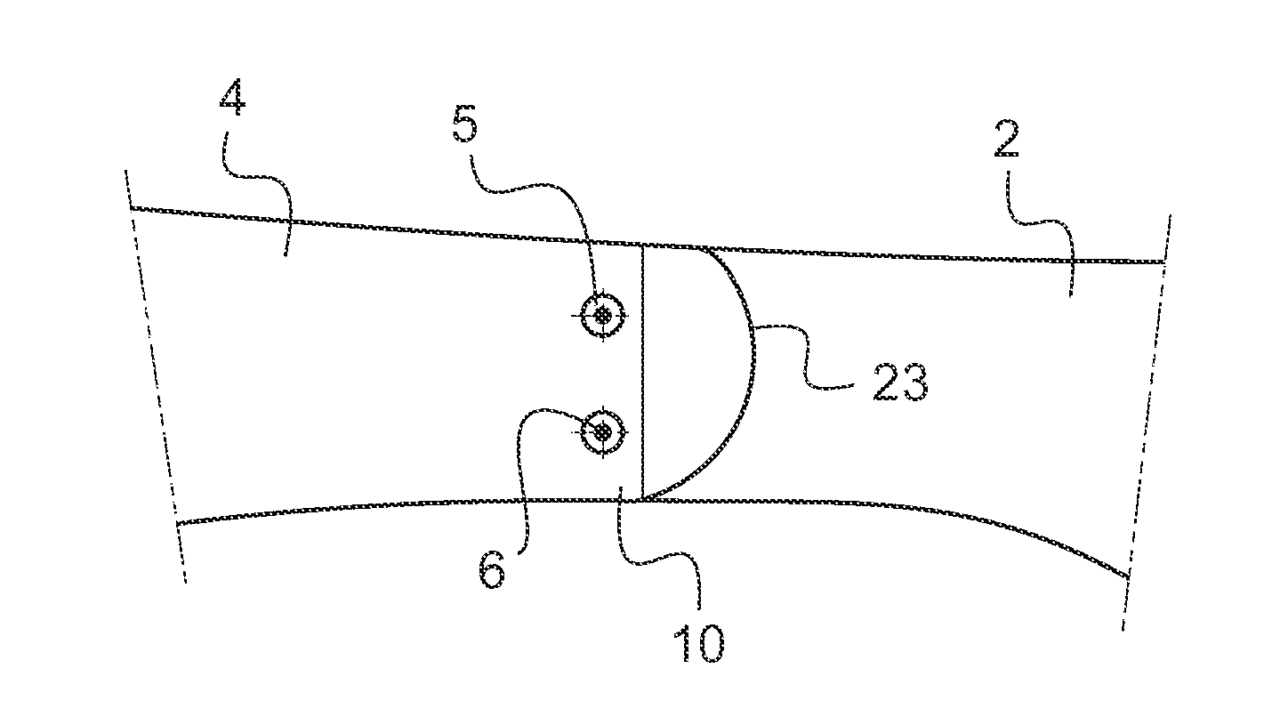
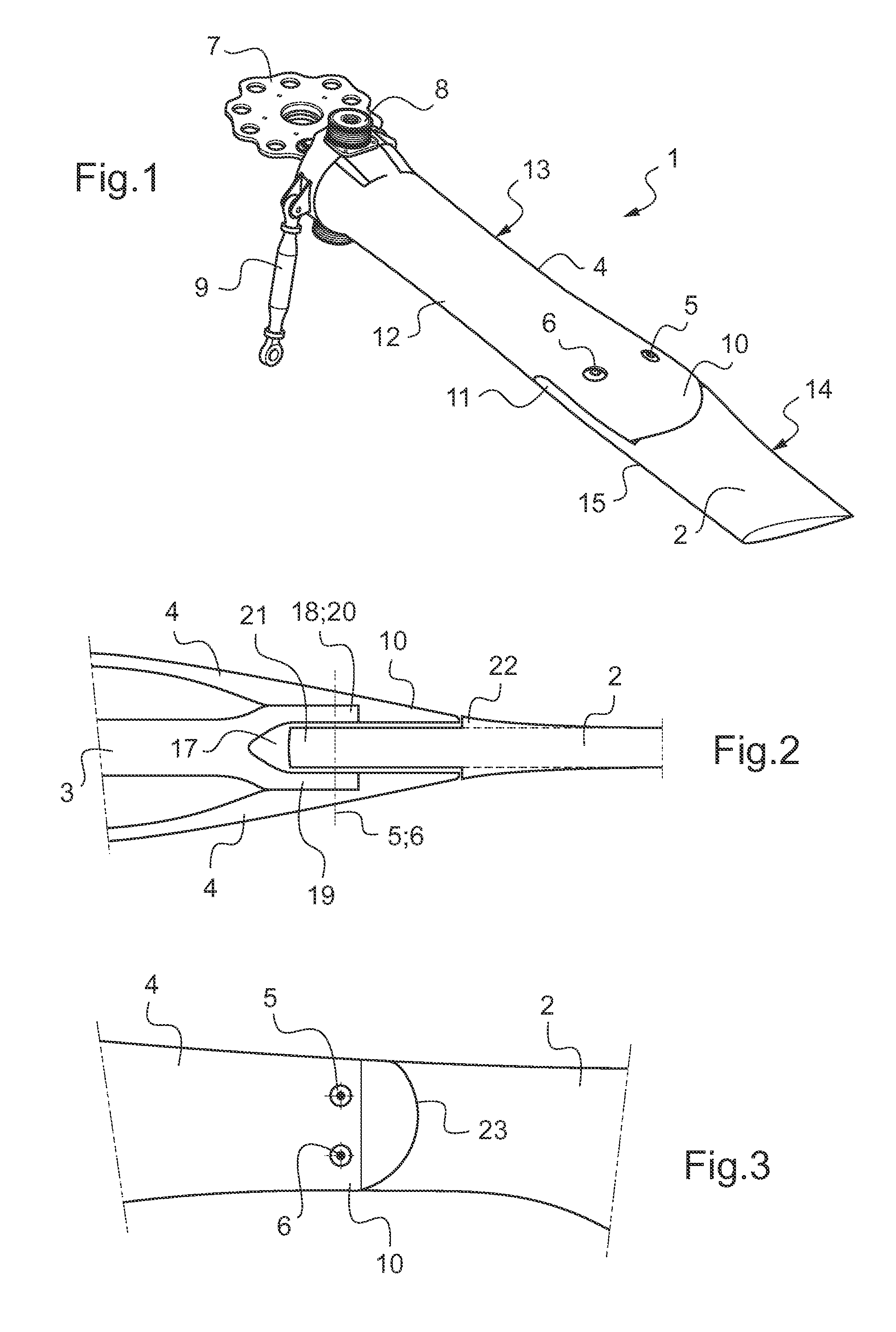
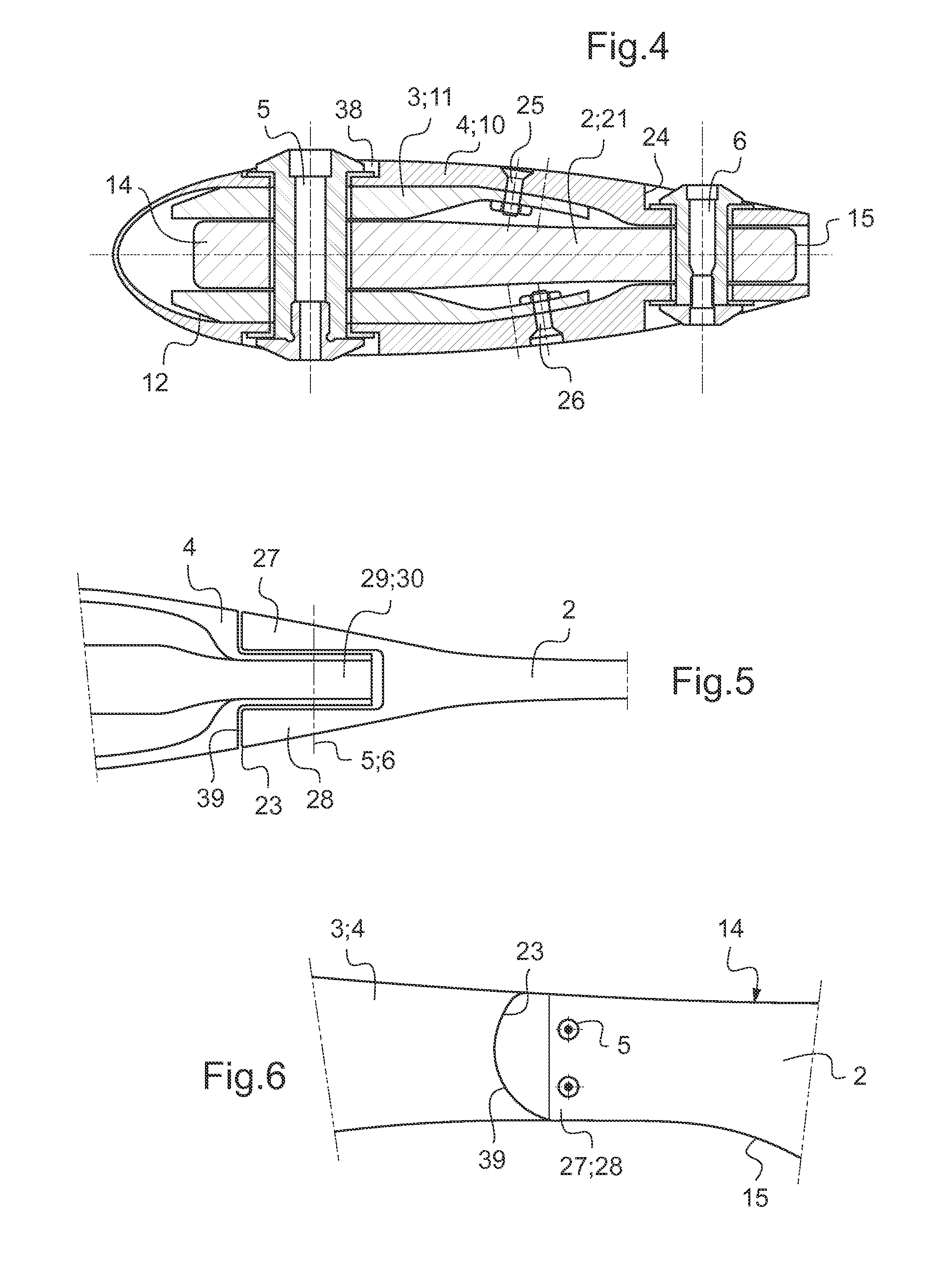
[0042]According to FIG. 1 an aerodynamic blade attachment 1 for a bearingless rotor of a helicopter (not shown) comprises an airfoil blade 2 and a flexbeam (see FIGS. 2, 4 and 5) inside a torsion stiff control cuff or torque tube 4 enclosing the flexbeam. The airfoil blade 2 is mounted by means of two removable fasteners 5, 6 to the flexbeam and the control cuff 4.

[0043]The two removable fasteners 5, 6 comprise a main bolt 5 and a supporting bolt 6. The main bolt 5 is conceived to carry higher loads than the supporting bolt 6.

[0044]The root end 42 of the flexbeam is mounted to a rotor head 7. A lead lag damper 8 is arranged on the control cuff 4 next to the rotor head 7. A pitch control 9 is mounted to the control cuff 4.

[0045]The control cuff 4 is provided with fairing means 10 with a smooth transition area from the control cuff 4 to a root end of said airfoil blade 2. The control cuff 4 is further provided with a rearward slit 11 along a peak of a trailing edge 12 of the control c...


PUM


Abstract

An aerodynamic blade attachment (1) for a bearingless rotor, particularly a main rotor, of a helicopter, comprising: an airfoil blade (2) having a tip end and a root end and having a pitch axis from said tip end to said root end; a flexbeam (3); a control cuff (4, 22) enclosing and extending along said flexbeam (3) and a separable junction arrangement between said flexbeam (3), said control cuff (4) and said root end of said airfoil blade (2). Said junction arrangement is mechanical between said flexbeam (3), said control cuff (4) and said root end of said airfoil blade (2). Removable fasteners (5, 6) connect said root end of said airfoil blade (2) and said control cuff (4) with said flexbeam (3). Said junction arrangement comprises fairing means (10, 27, 28, 31, 32 and 39) encompass the removable fasteners (5, 6) and said flexbeam (3).

Description

CROSS REFERENCE TO RELATED APPLICATIONS[0001]This application claims priority to European patent application No. EP 12 400014.2 filed on Apr. 18, 2012, the disclosure of which is incorporated in its entirety by reference herein.BACKGROUND OF THE INVENTION[0002](1) Field of the Invention[0003]The invention relates to an aerodynamic blade attachment for a bearingless rotor of a helicopter, including a lift-generating airfoil blade, a flexbeam enclosed by a control cuff or torque tube, and a connection means forming a separable or releasable junction between the airfoil blade and the flexbeam and the control cuff. The flexbeam and the control cuff can be connected or not.[0004](2) Description of Related Art[0005]During operation, the rotor blades are deflected in various directions and are thereby subjected to high loads in these various directions. The rotor blades must be designed to withstand these high loads while still providing the required flexibility or articulation to allow th...

Claims


Application Information

Patent Timeline
IPC IPC(8): B64C27/33
CPCB64C27/33B64C27/48B64C27/50B64C27/473
Inventor KUNTZE-FECHNER, GERALDBAUER, MARKUSORTNER, MARTIN
Owner AIRBUS HELICOPTERS DEUT GMBH
Why Eureka
Try Eureka