
Battery charger for electric vehicles

Active Publication Date: 2013-11-28
ABB E-MOBILITY BV
View PDF16 Cites 28 Cited by
  • Summary
  • Abstract
  • Description
  • Claims
  • Application Information

AI Technical Summary

Benefits of technology

This patent is about a battery charger for electric vehicles. The charger has three identical modules that control the current of the electric current output. These modules are connected in parallel to the vehicle's battery charging terminal. The technical effect is a more efficient and reliable battery charging system for electric vehicles.

Problems solved by technology

Both types of battery chargers require the use of high quality electronic components that can withstand high voltages and high currents and are therefore relatively expensive.

Method used


Image

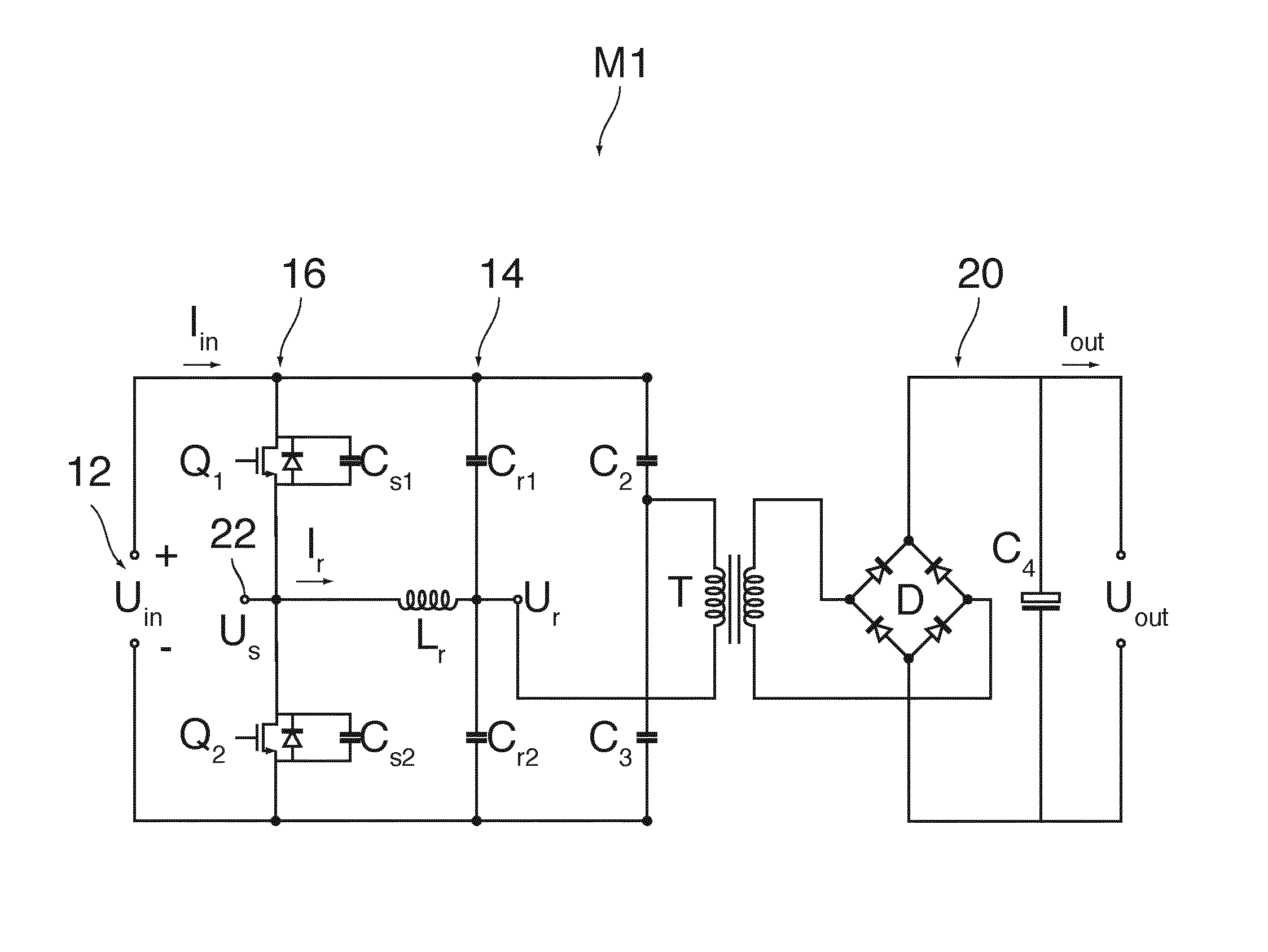
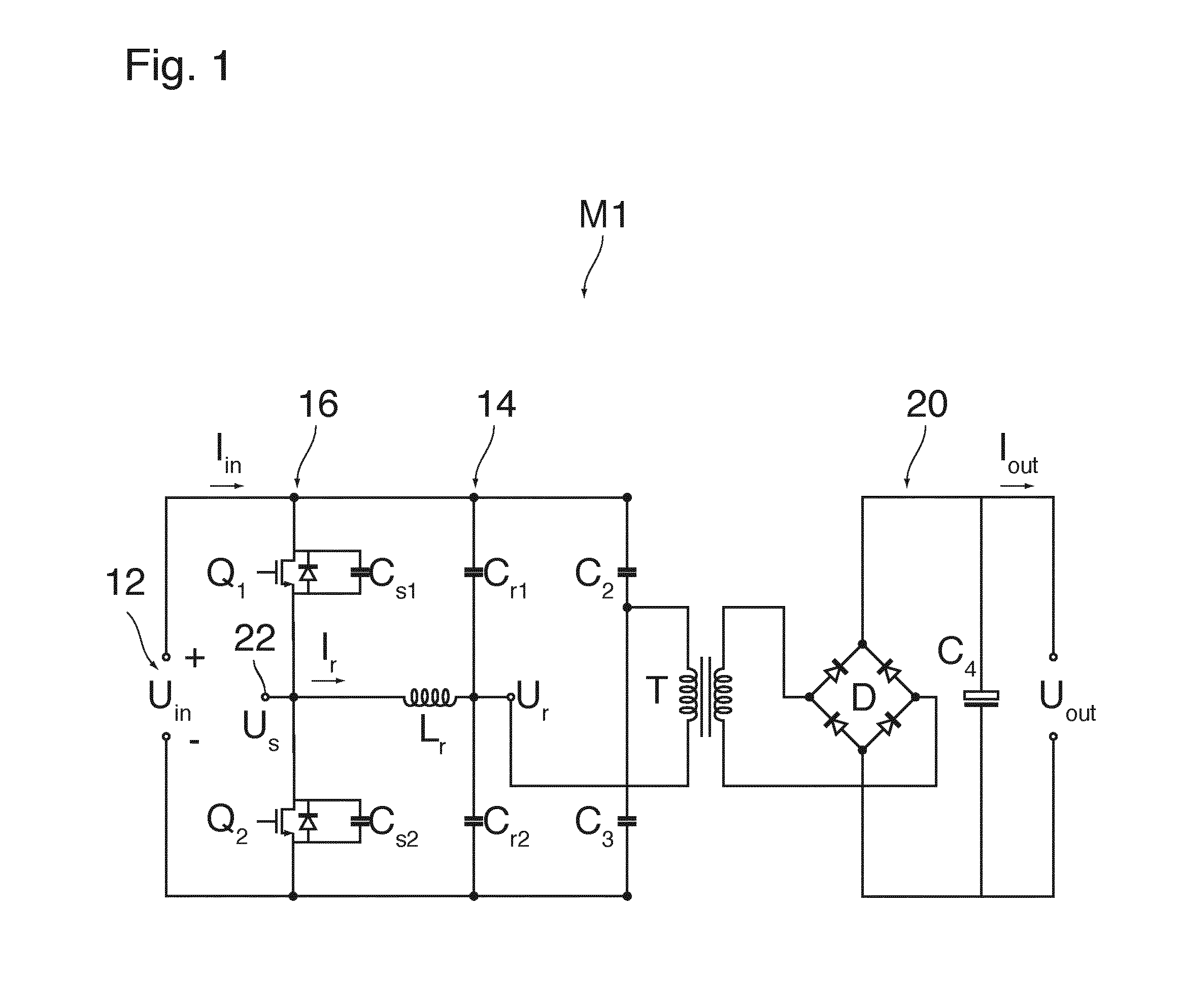
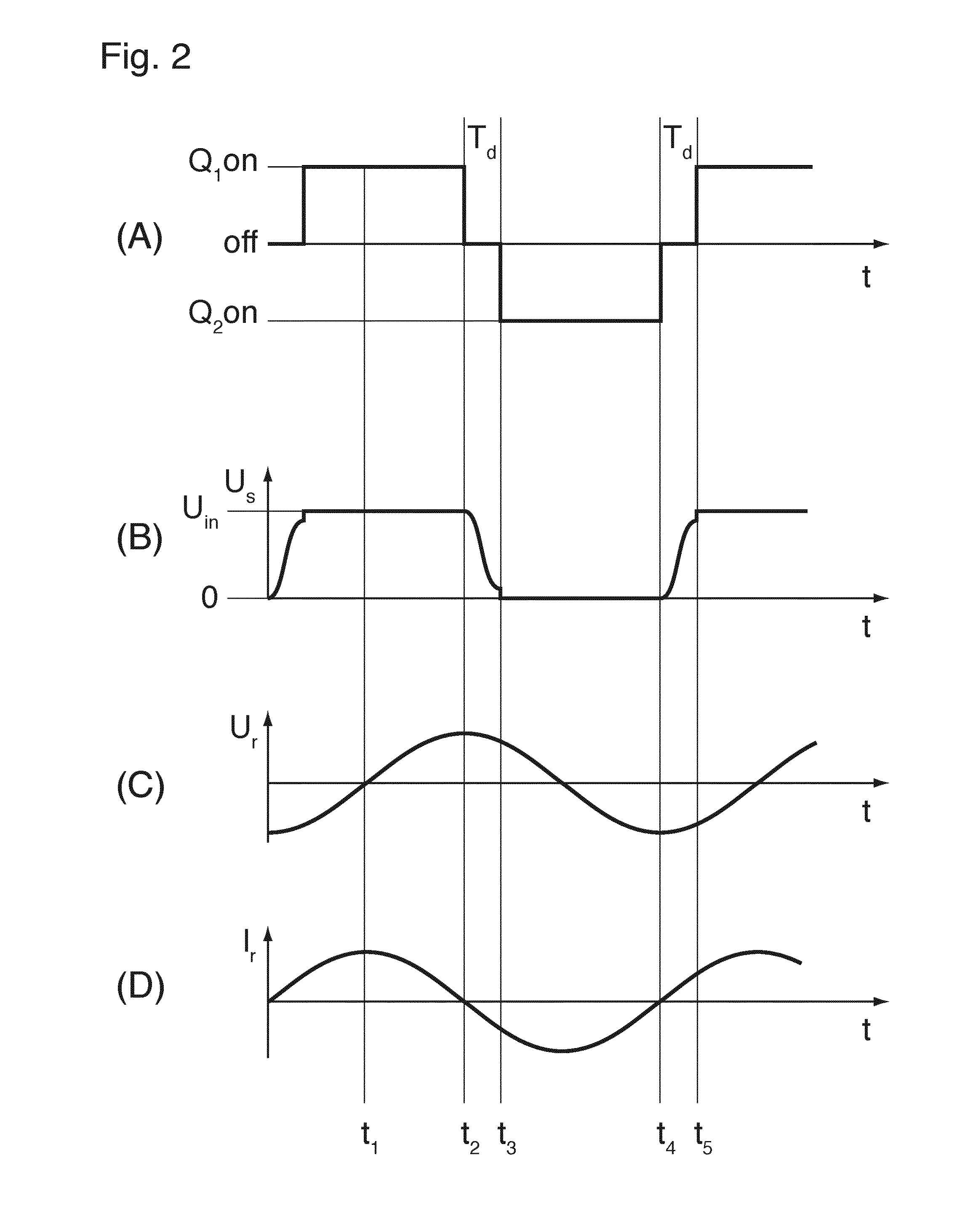
  • Battery charger for electric vehicles
  • Battery charger for electric vehicles
  • Battery charger for electric vehicles

Examples


Embodiment Construction

[0020]Exemplary embodiments of the present disclosure provide a reliable battery charger that can be manufactured at low costs.

[0021]In accordance with an exemplary embodiment, the battery charger according to the present disclosure is composed of at least three identical current controlled AC-DC converter modules having reverse current protected outputs connected in parallel to a charge terminal of the battery.

[0022]Since the converter modules can be current controlled while the output voltages of all modules can be determined by the battery voltage and are thus equal, it is possible to connect the outputs together, so that the charge current into the battery will be the sum of the currents provided by the individual modules. Thus, the modules may be designed for lower peak currents, so that less expensive components may be used. Since each charger is composed of a plurality of modules, mass production of the modules leads to further cost reductions. The output of each module is pr...


PUM


Abstract

A battery charger for electric vehicles includes at least three identical current controlled AC-DC converter modules having reverse current protected outputs connected in parallel to a charge terminal of the battery.

Description

RELATED APPLICATIONS[0001]This application claims priority as a continuation application under 35 U.S.C. §120 to PCT / EP2012 / 050813, which was filed as an International Application on Jan. 19, 2012 designating the U.S., and which claims priority to European Application 11151395.8 filed in Europe on Jan. 19, 2011. The entire contents of these applications are hereby incorporated by reference in their entireties.FIELD[0002]The present disclosure relates to a battery charger for electric vehicles.BACKGROUND INFORMATION[0003]Known battery chargers for electric vehicles can be either configured as on-board chargers adapted to be built in on board of the vehicle or as stationary fast chargers installed in a power station. On-board chargers can be plugged to a single phase 230V-16 A mains power socket at the home of the user so that the battery may be charged overnight with a charging power in the order of magnitude of 3.5 kW. Fast chargers may be powered by a 3-phase 400 V-40 A mains sourc...

Claims


Application Information

Patent Timeline
IPC IPC(8): B60L11/18
CPCB60L11/1811B60L2210/30H02J1/108H02M7/23Y02T90/14B60L3/00Y02T10/92Y02T10/7072B60L53/22B60L53/20B60L58/18B60L58/26H02J7/02H02J2207/20Y02T10/72Y02T10/70Y02T90/12H02M1/0048
Inventor KARDOLUS, MENNOSCHIJFFELEN, JOSGRONINGER, MARKVAN CASTEREN, DOLF
Owner ABB E-MOBILITY BV
Learn More