
Rotor and motor including the rotor

Inactive Publication Date: 2013-11-28
JTEKT CORP
View PDF14 Cites 6 Cited by
  • Summary
  • Abstract
  • Description
  • Claims
  • Application Information

AI Technical Summary

Benefits of technology

The patent text describes an invention that aims to provide technical effects that improve upon existing technologies. These effects may include increased efficiency, enhanced functionality, or improved performance. The invention may be developed by a team of researchers or a company with advanced technology. The patent text uses like numerals to describe elements that have similar functions or features.

Problems solved by technology

However, in order to increase the magnetic flux density at the outer periphery of a rotor core in a conventional configuration, there has been actually no other choice but to use permanent magnets that have a larger maximum energy product.
In addition, there is a limit on enhancement of performance of permanent magnets.

Method used


Image

  • Rotor and motor including the rotor
  • Rotor and motor including the rotor
  • Rotor and motor including the rotor

Examples


Embodiment Construction

[0017]Hereinafter, embodiments of the invention will be described with reference to the accompanying drawings.

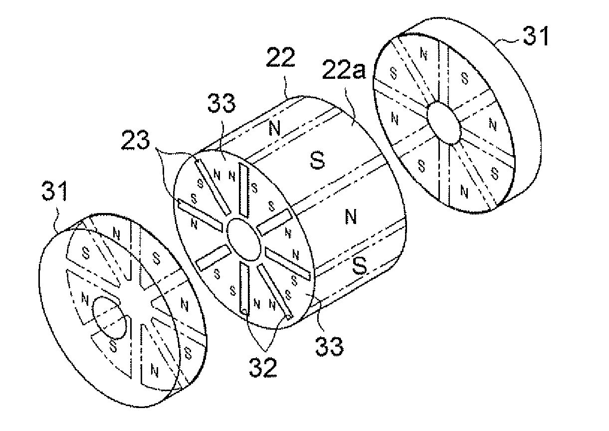
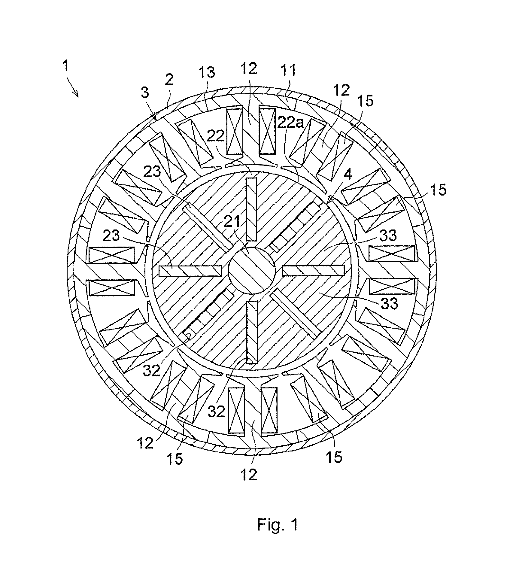
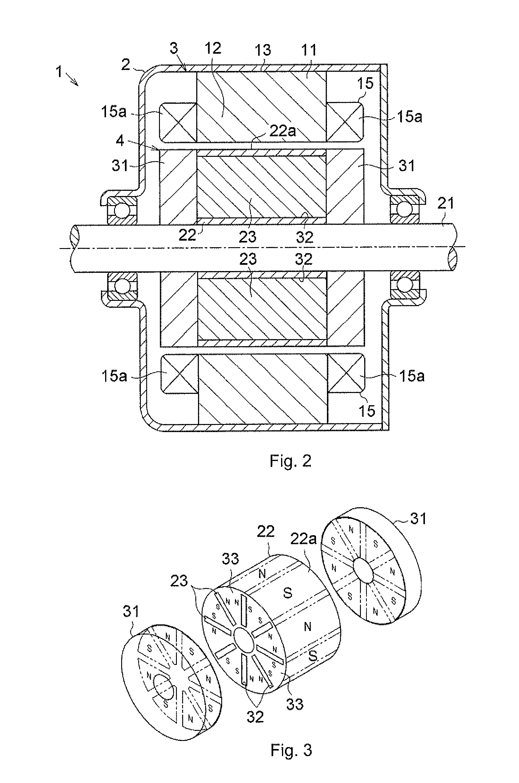
[0018]A motor 1 shown in FIG. 1 and FIG. 2 is installed in, for example, a vehicle, and used as a drive source for an electric power steering system that assists a steering operation, or as a drive source for an electric pump system that generates hydraulic pressure. As shown in FIG. 1, the motor 1 includes a stator 3 housed in a cylindrical case 2, and a rotor 4 that is arranged radially inward of the stator 3 and rotatably supported.

[0019]The stator 3 has a stator core 13 formed of a cylindrical portion 11 that is fixed to the inner periphery of the case 2, and a plurality of (twelve, in the present embodiment) teeth 12 extending radially inward from the cylindrical portion 11. Multiple (twelve, in the present embodiment) coils 15 are wound around the respective teeth 12.

[0020]The rotor 4 includes a rotary shaft 21, a cylindrical rotor core 22 that is fixed to the rotary s...


PUM


Abstract

A rotor includes a rotor core, a plurality of embedded magnets that are fixedly embedded in the rotor core, and end magnets provided on respective axial sides of the rotor core. The end magnets are formed by magnetizing magnetic material such that magnetic poles of the end magnets are provided at such positions as to axially face magnetic path portions serving as magnetic paths for magnetic fluxes of the embedded magnets, the magnetic fluxes passing through an outer periphery of the rotor core and each magnetic pole of the end magnet has the same polarity as the polarity of the magnetic pole of the embedded magnets, which appears in a corresponding one of the magnetic path portions.

Description

INCORPORATION BY REFERENCE / RELATED APPLICATION[0001]This application claims priority to Japanese Patent Application No. 2012-120145 filed on May 25, 2012 the disclosure of which, including the specification, drawings and abstract, is incorporated herein by reference in its entirety.BACKGROUND OF THE INVENTION[0002]1. Field of the Invention[0003]The invention relates to a rotor and a motor including the rotor.[0004]2. Discussion of Background[0005]Japanese Patent Application Publication No. 2010-233346 (JP 2010-233346 A) describes a motor including a so-called embedded magnet-type rotor in which permanent magnets are embedded and fixed in a rotor core. In the motor including the embedded magnet-type rotor, not only magnetic torque from the permanent magnets but also reluctance torque is generated. Therefore, the motor including the embedded magnet-type rotor has an advantage over a motor including a so-called surface permanent magnet rotor in which permanent magnets are fixed onto th...

Claims


Application Information

Patent Timeline
IPC IPC(8): H02K1/27
CPCH02K1/2773H02K1/2706H02K1/2766H02K1/276H02K1/2713
Inventor SHIBATA, YOSHIYUKI
Owner JTEKT CORP
Learn More