
Resonance coupling wireless power transfer receiver and transmitter

a wireless power transfer and receiver technology, applied in the direction of transformers, inductances, transportation and packaging, etc., can solve the problems of low transmission efficiency of long distance power transmission, inductance coupling method limitations, heating by eddy currents, etc., to reduce the total power consumption of the receiver and reduce the power generation

Inactive Publication Date: 2013-11-21
ELECTRONICS & TELECOMM RES INST
View PDF4 Cites 15 Cited by
  • Summary
  • Abstract
  • Description
  • Claims
  • Application Information

AI Technical Summary

Benefits of technology

The patent describes a device that adjusts the resistance in a circuit to control the flow of electric current. The device can increase or decrease the input resistance as the load on the circuit increases or decreases. This can help improve power generation by the device's power source. The overall technical effect is to improve the efficiency and effectiveness of power transmission in the circuit.

Problems solved by technology

However, the inductive coupling method has limitations such as low transmission efficiency in long distance power transmission, heating by eddy currents, and difficulties in case of charging a plurality of devices.

Method used


Image

  • Resonance coupling wireless power transfer receiver and transmitter
  • Resonance coupling wireless power transfer receiver and transmitter
  • Resonance coupling wireless power transfer receiver and transmitter

Examples


Embodiment Construction

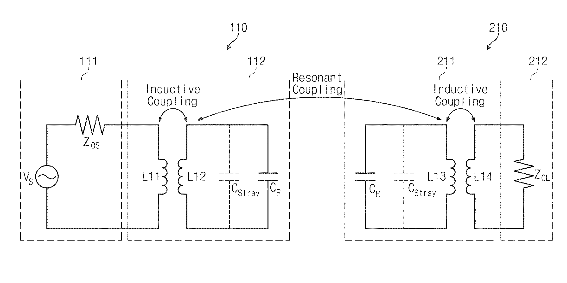
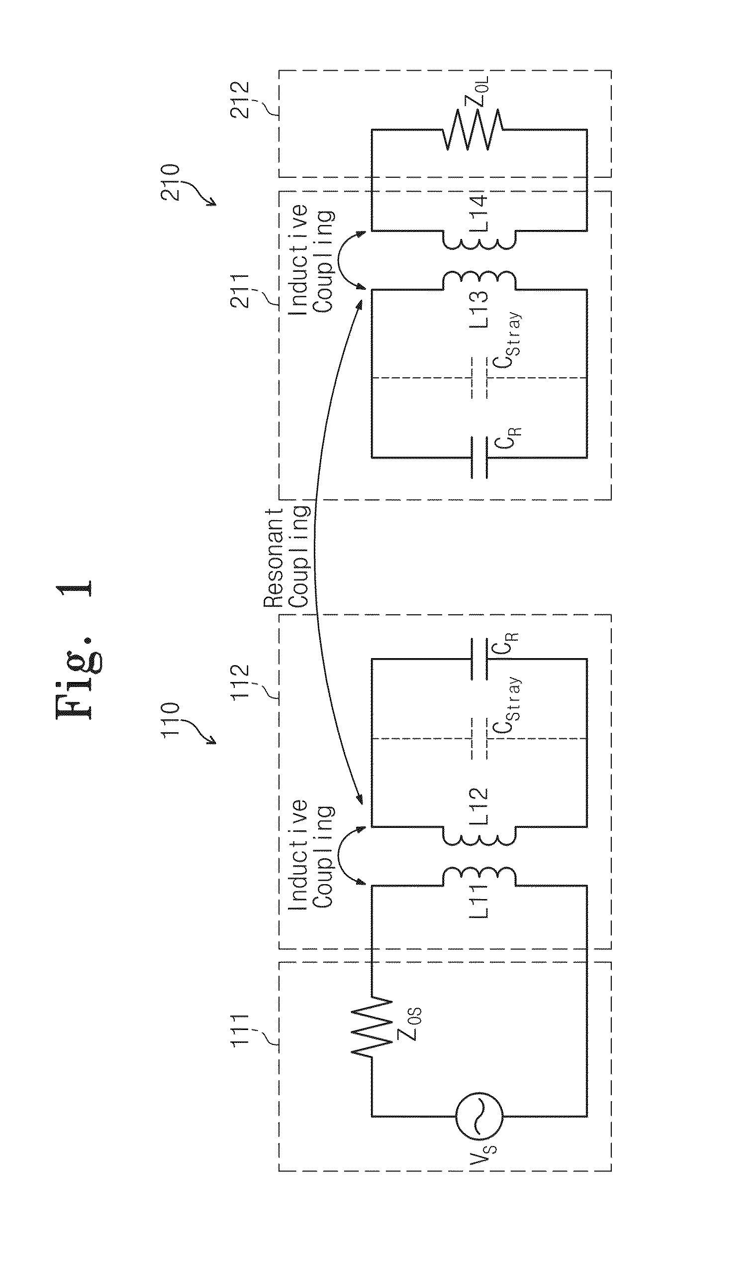
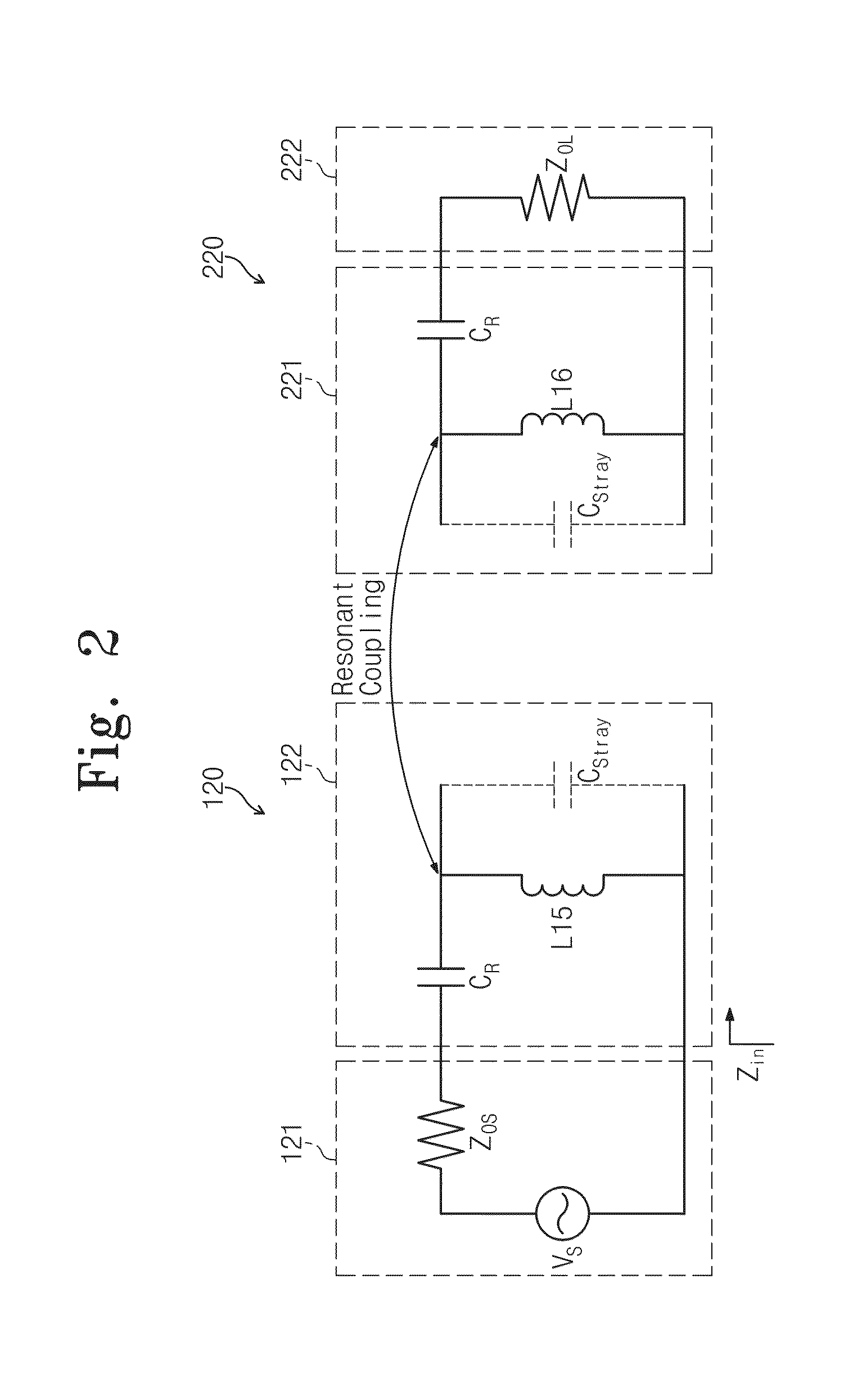
[0034]The general explanation above and following specification must be understood as an example and must be considered as providing an additional explanation of a claimed invention. Reference marks are presented specifically in exemplary embodiments of the present invention and this example is illustrated on reference drawings. In any possible case, the same reference numbers are used in a specification and a drawing for referring to the same or the similar part.

[0035]A resonance-coupled wireless power receiver and transmitter is used above as an example for explaining characteristics and functions of the present invention. However, those skilled in the art can easily understand other advantages and performance of the present invention according to the contents desccribed herein.

[0036]The present invention is also embodied or applied in different embodiments. Besides, the specification within the scope, the technical features, and the other purpose of the present invention may be m...


PUM

PropertyMeasurementUnit
poweraaaaaaaaaa
impedanceaaaaaaaaaa
resistanceaaaaaaaaaa

Abstract

Provided are a wireless power transmission receiver and a system including the same, particularly to a receiver and transmitter transmitting power from one transmitter to a plurality of receivers at the same time by wireless. According to the present invention, the wireless power receiver comprises a receiving coil unit receiving power from a transmitter by a resonance coupling method; and a power receiving unit receiving power from the receiving coil unit to provide the power to a load resistor, wherein an input impedance of the power receiving unit is adjusted according to power consumed by a plurality of receivers. Therefore, power transmission efficiency of the wireless power receiver and transmitter can be improved.

Description

CROSS-REFERENCE TO RELATED APPLICATIONS[0001]This U.S. non-provisional patent application claims priority under 35 U.S.C. §119 of Korean Patent Application No. 10-2012-0051952, filed on May 16, 2012, the entire contents of which are hereby incorporated by reference.BACKGROUND OF THE INVENTION[0002]The present invention disclosed herein relates to a wireless power transmission system wherein power is transmitted to a plurality of receivers from one transmitter at the same time by wireless.[0003]Recently, interest in wireless power transmission is increasing. In wireless power transmission, power is transmitted through a free space instead of using a cable. As the user mobile electronic devices increases, there is increasing demand for wireless devices capable of supplying power to distant places.[0004]Wireless power transmission may be classified into an electromagnetic wave radiation method and a magnetic field inductive coupling method. The magnetic field inductive coupling method ...

Claims


Application Information

Patent Timeline
Patent Type & Authority Applications(United States)
IPC IPC(8): H01F38/14H02J17/00
CPCH02M3/3376H02J50/12H02J50/40B60C23/0413H01F38/14H02J50/005H04B5/24H04B5/79
Inventor CHEON, SANG HOONKIM, YONG HAELEE, MYUNG LAEKANG, SEUNG YOULZYUNG, TAEHYOUNG
Owner ELECTRONICS & TELECOMM RES INST
Learn More