Laser cutting method optimized in terms of mass defect per unit length
- Summary
- Abstract
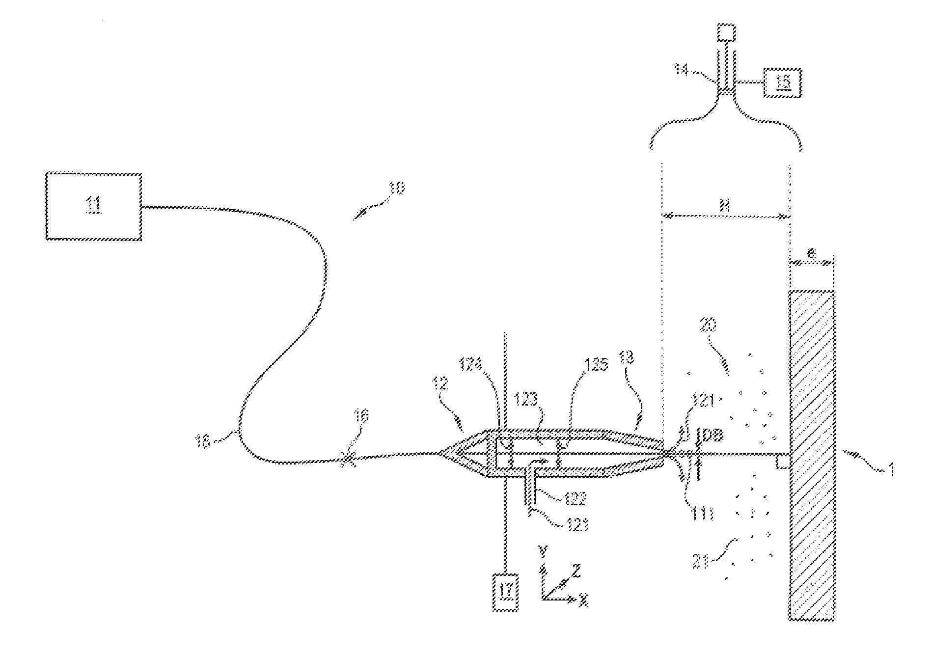
- Description
- Claims
- Application Information
AI Technical Summary
Benefits of technology
Problems solved by technology
Method used
Image


Examples
Embodiment Construction
[0015]The invention proposes overcoming at least one of these drawbacks.
[0016]To this end, according to the invention an optimized laser cutting method for cutting out a piece from a material by a cutting system is proposed and comprises[0017]a laser source for producing a laser beam having a power, and[0018]a cutting head comprising an end nozzle for the passage of the cutting laser beam,
wherein the method is characterized in that it comprises a step of determining a cutting power Pd such that:
Pd=Max(Popt;λe)
where Max is the mathematical operator of the maximum,
[0019]Popt is an optimal power of the laser beam of the cutting system, determined in accordance[0020]with the piece to be cut out, and / or[0021]with cutting parameters and / or[0022]with the type of system,
in order to minimize the mass defect per unit length of the piece during cutting of said piece,
[0023]λ is a leading coefficient representing the number of kW required for cutting out the piece per mm of piece thickness, and
[...
PUM
| Property | Measurement | Unit |
|---|---|---|
| Length | aaaaa | aaaaa |
| Length | aaaaa | aaaaa |
| Length | aaaaa | aaaaa |
Abstract
Description
Claims
Application Information
 - R&D
- Intellectual Property
- Life Sciences
- Materials
- Tech Scout
- Unparalleled Data Quality
- Higher Quality Content
- 60% Fewer Hallucinations
Browse by: Latest US Patents, China's latest patents, Technical Efficacy Thesaurus, Application Domain, Technology Topic, Popular Technical Reports.
© 2025 PatSnap. All rights reserved.Legal|Privacy policy|Modern Slavery Act Transparency Statement|Sitemap|About US| Contact US: help@patsnap.com