
Security device for a pedal vehicle

a technology for security devices and pedal vehicles, applied in the field of security devices, can solve the problems of easy damage or breakage of known security devices such as padlocks, chains and u-locks, and the device is relatively thin, and achieves the effect of improving the fit of the device and reducing the movement of the devi

Inactive Publication Date: 2013-11-14
GRAY DEREK
View PDF25 Cites 1 Cited by
  • Summary
  • Abstract
  • Description
  • Claims
  • Application Information

AI Technical Summary

Benefits of technology

The device provides enhanced security by preventing pedaling and freewheeling, is easier to fit and remove, and can be adapted to different vehicle sizes, reducing the risk of damage and improving usability.

Problems solved by technology

Unfortunately, known security devices such as padlocks, chains and U-locks are susceptible to being damaged or broken by a thief in an attempt to steal a bicycle secured by known security devices.
One of the reasons for the inherent weakness of known security devices is that such devices have relatively thin, elongate, loose fitting parts that make them open to attack.
As a result, the security devices are difficult to carry because of their size and become awkward to fit in a secure position around the vehicle being secured.
A further disadvantage of known security devices is that their dimensions and shape result in a loose fit between the pedal vehicle being secured and the security device thus creating a lot of space, or play, which might result in damage to the vehicle or provide a thief with further points of leverage, thus making it easier for the device to be broken.
Yet another disadvantage of known security devices is their fixed size, which restricts the number of pedal vehicles that it can be secured to.
Therefore, known security devices are not, in general, interchangeable between different pedal vehicles and are typically configured to secure only a specific pedal vehicle model.

Method used


Image

  • Security device for a pedal vehicle
  • Security device for a pedal vehicle
  • Security device for a pedal vehicle

Examples


Embodiment Construction

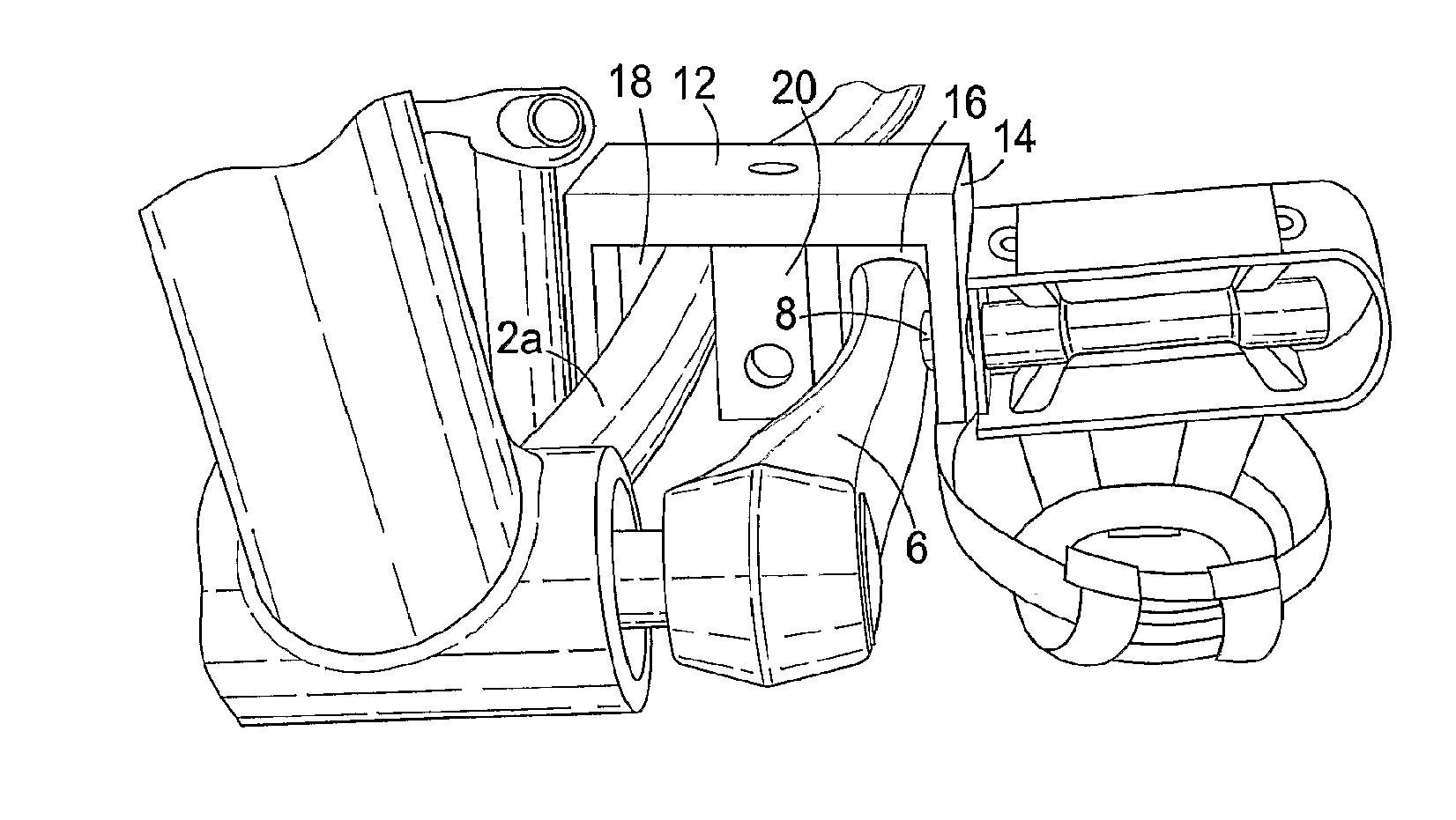
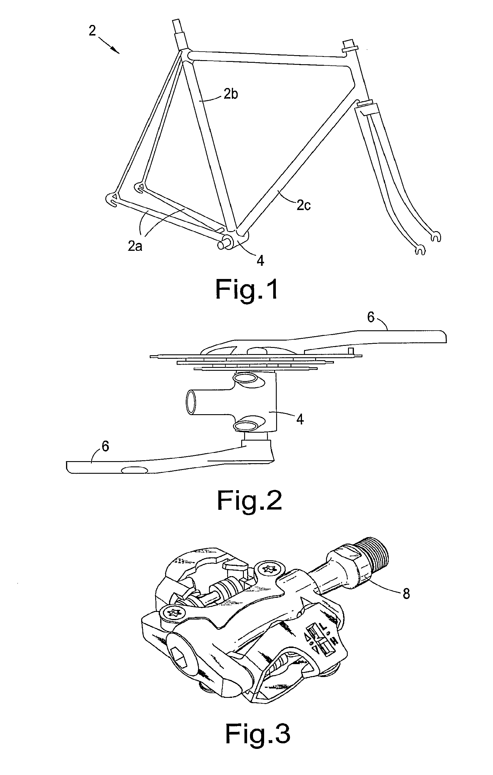
[0094]Referring to FIGS. 1 to 3 of the drawings, a pedal vehicle frame 2 is shown comprising chain stays 2a, a seat tube 2b and a down tube 2c. FIG. 2 shows a bottom bracket shell 4 of the frame 2 with a pedal crank arm 6 located on either side of the bottom bracket shell. FIG. 3 is a perspective view of a conventional pedal having a pedal axle 8 extending therefrom, the screw thread portion of the pedal axle configured to be attachably received in a distal end of a pedal crank arm by screwing the pedal onto a crank arm.

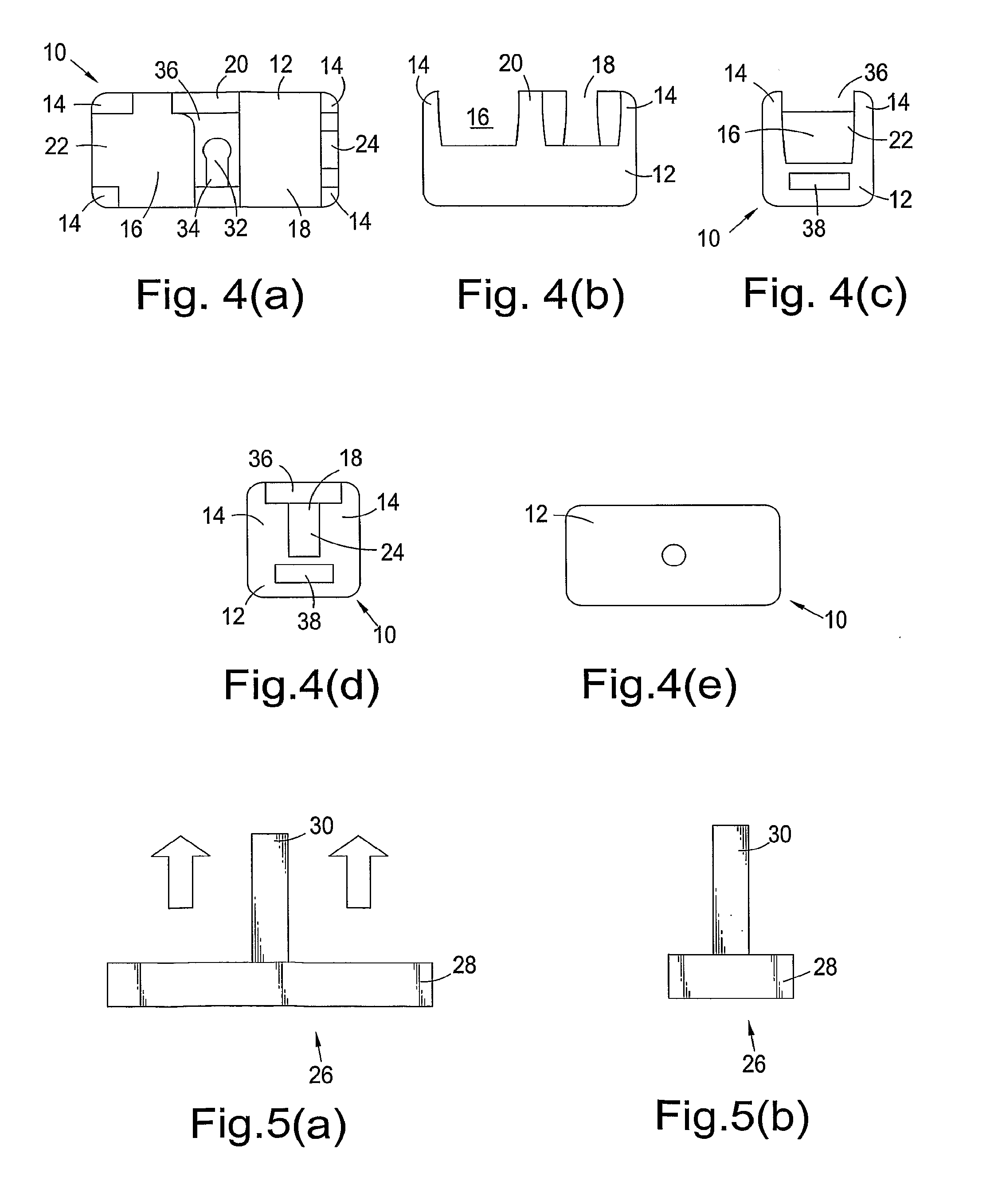
[0095]In light of the teaching of the present invention it will be clear and unambiguous to the skilled person that there are a number of components and integers common to the embodiments described below. In particular, each security device has a structure, or body, having through-hole means. The through-hole means, formed by the structure, define the openings or spaces in which parts of a pedal vehicle can be releasably secured.

[0096]A linked structure, which may ta...


PUM


Abstract

A security device can be secured to a pedal vehicle to prevent the vehicle being pedalled. The security device includes a receiving means and a securing means. The receiving means may include a through-hole means for receiving part of a frame and a pedal crank arm of the vehicle and may have an open configuration in which the frame part and a part of the crank can be placed in the through-hole means, and a closed configuration in which a frame part and crank arm are held in the through-hole means against relative movement therebetween.

Description

CROSS-REFERENCE TO RELATED APPLICATIONS [0001]The present application is a continuation of U.S. patent application Ser. No. 12 / 992,250, filed May 13, 2009, which is a national phase application of PCT application PCT / GB2009 / 001200 filed pursuant to 35 U.S.C. §371, on May 13, 2009, which claims priority to GB 0808763.7, filed May 14, 2008. All applications are incorporated herein by reference in their entirety and for all purposes.TECHNICAL FIELD [0002]This invention relates to a security device for attaching to a pedal vehicle to prevent the vehicle from being pedalled. The invention further relates to a security device, which can also prevent a pedal, or wheeled vehicle from being free-wheeled, or used in a conventional manner.BACKGROUND [0003]Security devices such as chains, padlocks and U-locks are commonly used to secure parts of a pedal vehicle to immovable objects such as railings or bicycle stands. By way of example, a padlock and chain combination would secure a pedal vehicl...

Claims


Application Information

Patent Timeline
Patent Type & Authority Applications(United States)
IPC IPC(8): B62H5/10
CPCB62H5/10Y10T70/5876Y10T70/5872Y10T70/5881Y10T70/40Y10T70/5885B62H5/14
Inventor GRAY, DEREK
Owner GRAY DEREK
Learn More