
Apparatus and Method for Achieving a Head Up Posture for a 3-D Video Image for Operative Procedures in Dentistry

Inactive Publication Date: 2013-11-07
PARKER WILLIAM S
View PDF15 Cites 7 Cited by
  • Summary
  • Abstract
  • Description
  • Claims
  • Application Information

AI Technical Summary

Benefits of technology

This patent describes an apparatus and method that connects a camera and monitor on a single arm, allowing the dentist to have a 3-D view of the operative site. The apparatus can accommodate differences in dentist height and provides a intuitive depth perception. It also includes a laser system that allows for quick movement and positioning of the apparatus, with minimal disruption to surgical procedures. The apparatus enables the dentist to easily observe and analyze the operative site, improving the accuracy and precision of dental procedures.

Problems solved by technology

The affected dentists suffer great economic losses which in aggregate are estimated to be $10 billion annually in the U.S. An individual dentist who retires early may lose 5-10 years of peak earning because of work related back and neck injury.
Loupes provide the wearer with needed magnification however, the narrow field of view and the weight of the loupes makes their use uncomfortable and often add to a dentist's poor posture and likelihood of neck and back injury.
These neck and back injuries are the most common cause of temporary and even permanent disability among dentists.
Operating Microscopes provide magnified images but the immobile, static nature of the eyepieces, combined with the awkward positions that must be assumed by the patient and the dentist, for proper viewing of many areas of dental anatomy, do not fully alleviate the poor posture or discomfort associated with doing dental procedures, and can exacerbate the discomfort.
These manipulations when programmed or set-up manually require a complex spatial understanding by the dentist and also require extended training on the apparatus; and sometimes require difficult set-up prior to performing dental procedures.
In addition, a monitor which is remotely located and which may be rigidly affixed to the wall often is not and cannot be positioned correctly to present the proper image orientation to the dentist performing surgery.
All these identified factors reduce the usefulness of the apparatus and inhibit its widespread use in dental surgeries.
When the set-up referenced above requires as much as two or three minutes and this set-up may be repeated two or three times for a given patient, the dentist's productivity suffers, the usefulness of the equipment is greatly compromised, and its use diminished.
All this manipulation is difficult and time consuming.

Method used


Image

  • Apparatus and Method for Achieving a Head Up Posture for a 3-D Video Image for Operative Procedures in Dentistry
  • Apparatus and Method for Achieving a Head Up Posture for a 3-D Video Image for Operative Procedures in Dentistry
  • Apparatus and Method for Achieving a Head Up Posture for a 3-D Video Image for Operative Procedures in Dentistry

Examples


Embodiment Construction

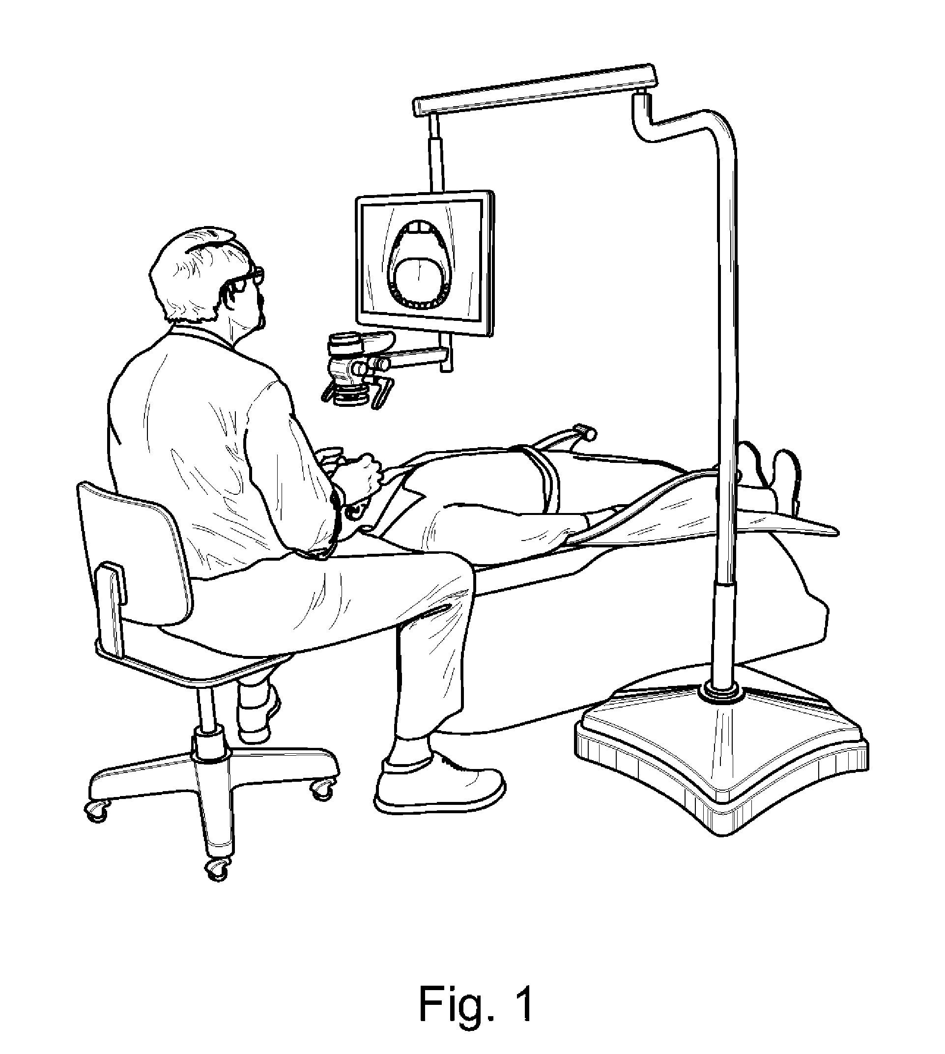
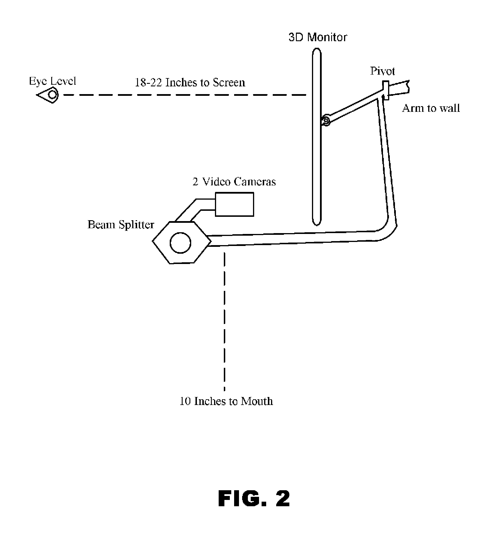
[0027]An object of this invention is to rigidly connect the imaging elements such as camera(s) and the monitor on a single arm, or a single arm element, which maintains the proper relationship between the camera and the monitor while simultaneously allowing the monitor height to be at the ideal viewing height for the dentist. This can be seen in FIG. 1 and is sketched in FIG. 2. While the imaging elements of the invention are rigidly connected on a single arm or arm element, there is provision for changing the tilt, on a horizontal axis, of the monitor, as well as its height, to accommodate differences in height among dentists. This rigid connection of the invention assures that the image of the operative site will always be presented in the most understandable frame of reference for the dentist.

[0028]It is further an object of this invention to a provide simple distance estimation from the objective lens of the optical apparatus and the mouth or dental tissue within the mouth, by m...


PUM


Abstract

An apparatus and method to rigidly connect the imaging elements such as camera(s) and the monitor on a single arm, or a single arm element, which maintains the proper relationship between the camera and the monitor while simultaneously allowing the monitor height to be at the ideal viewing height for the dentist. While the imaging elements of the invention are rigidly connected on a single arm or arm element, there is provision for changing the tilt, on a horizontal axis, of the monitor, as well as its height, to accommodate differences in height among dentists. This rigid connection of the invention assures that the image of the operative site will always be presented in the most understandable frame of reference for the dentist.

Description

[0001]This application is related to and claims priority to U.S. Provisional Patent application No. 61 / 617,461 filed Mar. 29, 2012. Application 61 / 617,461 is hereby incorporated by reference in its entirety.BACKGROUND[0002]1. Field of the Invention[0003]The present invention relates generally to performing dental work and more particularly to performing dentistry from a magnified video image in a comfortable head up posture.[0004]2. Description of the Prior Art and Problem[0005]Ten percent (10%) of the practicing dentists retire early; another twenty percent (20%) reduce their practice hours because of chronic neck and back pain and disabling neck injuries. The affected dentists suffer great economic losses which in aggregate are estimated to be $10 billion annually in the U.S. An individual dentist who retires early may lose 5-10 years of peak earning because of work related back and neck injury.[0006]Dental surgery requires that precision and detailed work be performed in a poorly...

Claims


Application Information

Patent Timeline
IPC IPC(8): A61B1/00A61B1/04A61B19/00A61B1/24
CPCA61B1/00048A61B1/24A61B1/04A61B1/00193A61B1/00009A61B1/0005A61G2203/20A61B19/5223A61B19/26A61B19/5225A61B2019/5227A61G13/10A61G15/14A61B1/00149A61B90/50A61B90/37A61B2090/371
Inventor PARKER, WILLIAM S.
Owner PARKER WILLIAM S
Learn More