
Digital control for a microelectromechanical element

a microelectromechanical element and digital control technology, applied in the field of digital control of microelectromechanical elements, can solve the problems of large integration area of constituent components, complex and expensive overall system having a comparatively high energy demand, and achieve the effect of reducing implementation complexity

Active Publication Date: 2013-11-07
ROBERT BOSCH GMBH
View PDF4 Cites 4 Cited by
  • Summary
  • Abstract
  • Description
  • Claims
  • Application Information

AI Technical Summary

Benefits of technology

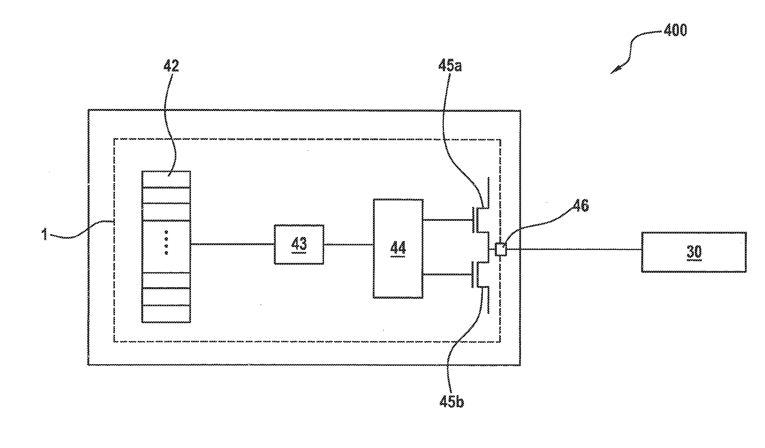
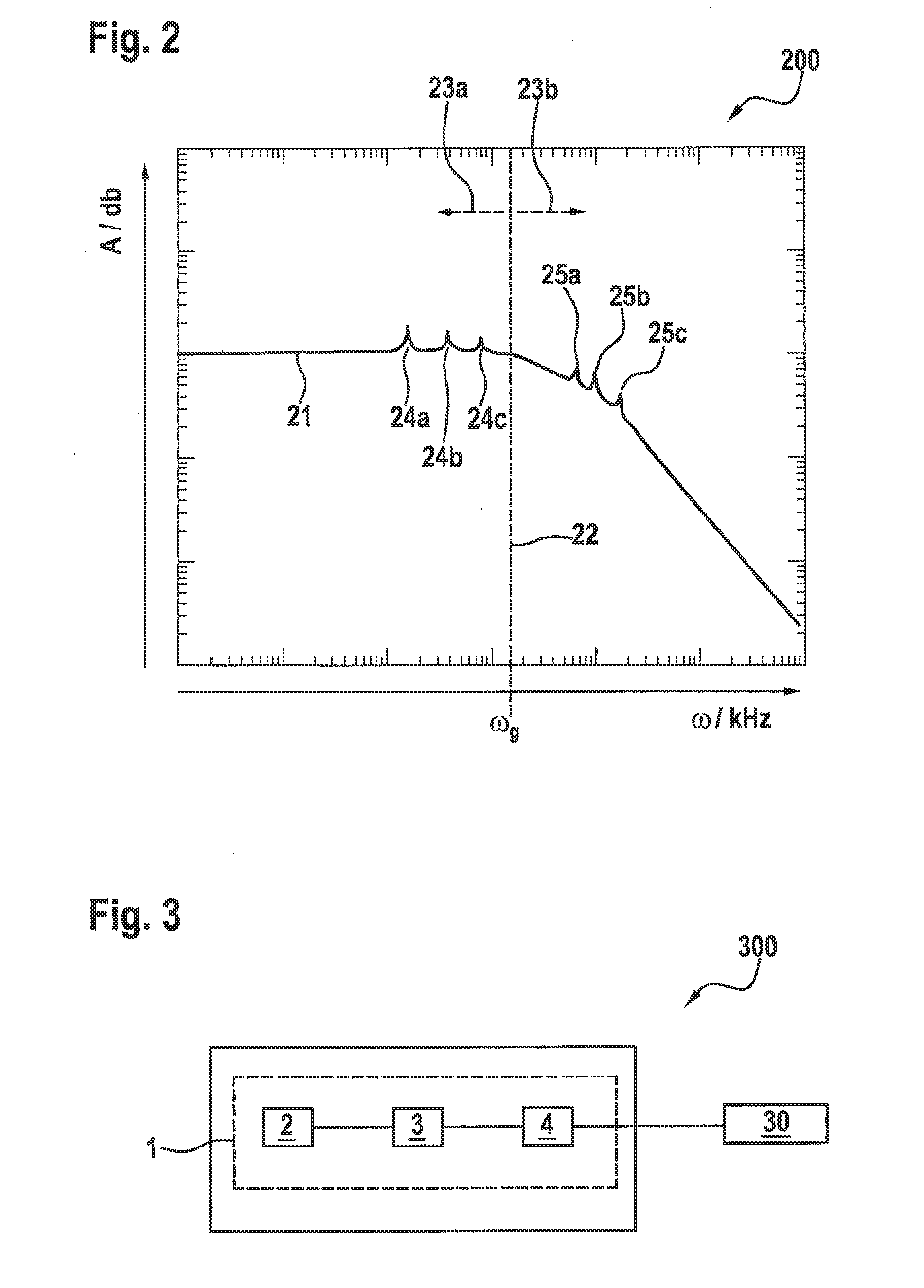
The present invention provides a method and device for triggering a microelectromechanical element during qui-static operation without interference and with minimal complexity. The device includes a waveform generator, a modulator, and a digital driver device. The modulator oversamples the digital trigger signal, subjecting it to noise shaping and outputting it to drive the microelectromechanical element. This technique offers the advantage of using conventional digital output stages in a simple and space-saving manner. The method also allows for a high deflection precision of the actuator during qui-static operation with little demands on the control drivers at the same time. The zeros in the modulator are set to frequencies of resonant modes of the microelectromechanical element, effectively targeting the suppression of noise components. This method effectively prevents the excitation of resonant modes of the microelectromechanical element during qui-static operation.

Problems solved by technology

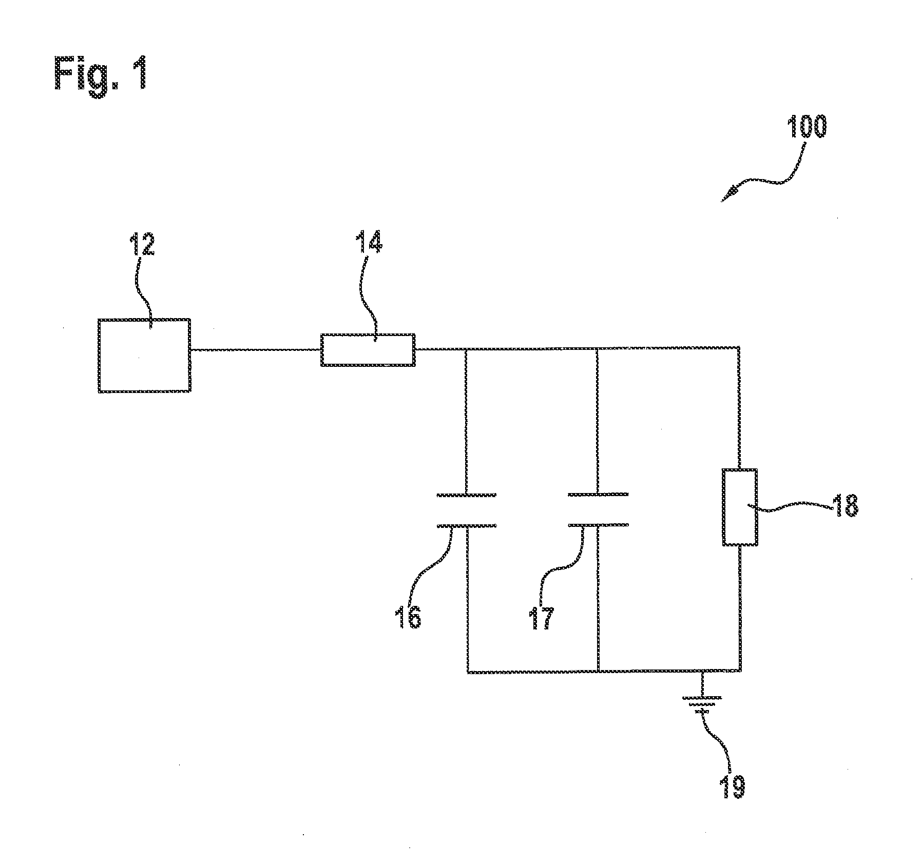
However, they require a relatively large area for the integration of the constituent components, such as operational amplifiers, controllers, voltage and current reference circuits, stabilization capacitors and similar components, for example.
Furthermore, a digital-analog converter is needed, which may result in a complex and expensive overall system having a comparatively high energy demand.

Method used


Image

  • Digital control for a microelectromechanical element
  • Digital control for a microelectromechanical element
  • Digital control for a microelectromechanical element

Examples


Embodiment Construction

[0025]The same reference numerals are used in the figures of the drawings for the same elements, features and components and those having the same function, unless otherwise indicated. It is understood that components and elements in the drawings are not necessarily depicted to scale for reasons of clarity and comprehensibility.

[0026]Microelectromechanical elements in the sense of the present invention may include in particular microelectromechanical actuators. Actuators are triggered by a trigger signal to induce input signals into mechanical actions, in particular rotation, tilting and linear offsetting of connected mechanical components. One example of an actuator is a micromirror actuator, using which a micromirror may be rotated or moved along one or multiple axes of rotation, tilt or offset.

[0027]During linear triggering of microelectromechanical components, an attempt is made not to stimulate any resonant modes of the microelectromechanical element, i.e., to permit quasi-stat...


PUM


Abstract

A control circuit for a microelectromechanical element includes: a waveform generator, which is designed to generate a digital trigger signal for the microelectromechanical element, a modulator, which is designed to oversample the digital trigger signal, to subject the signal to a noise shaping, and to output the oversampled and noise-shaped digital trigger signal; and a digital driver device, which is designed to drive the microelectromechanical element using the oversampled and noise-shaped digital trigger signal.

Description

BACKGROUND OF THE INVENTION[0001]1. Field of the Invention[0002]The present invention relates to a control circuit for a digital trigger for a microelectromechanical element and a method for triggering a microelectromechanical element.[0003]2. Description of the Related Art[0004]Microelectromechanical systems (MEMS) are used today in micro system technology as converters of trigger signals into mechanical actions. Actuators play a major role here, in particular microelectromechanical actuators. One exemplary application involves the use of micromirror actuators (SLM, spatial light modulators) with the help of which a micromirror element or a micromirror array may be deflected in a targeted manner by rotation, tilting and shifting of light beams such as laser beams, for example.[0005]Actuators require special and precise trigger signals to be able to ensure rapid, reproducible interference-free operation of the mechanical elements of the actuator. This makes high demands on the trigg...

Claims


Application Information

Patent Timeline
IPC IPC(8): H02P13/00
CPCH02P13/00G02B26/0833H02N1/002G02B26/08H02N1/00
Inventor AL DIBS, MOHAMAD IYADWENZLER, AXELKRAYL, OLIVER
Owner ROBERT BOSCH GMBH
Learn More