
Machine system having a lubrication system

a lubrication system and machine technology, applied in the direction of engine lubrication, pressure lubrication, engine cooling apparatus, etc., can solve the problems of low power loss of the machine, different moving parts' service life, etc., and achieve the effect of improving the lubrication system

Inactive Publication Date: 2013-10-31
VESTAS WIND SYST AS
View PDF13 Cites 10 Cited by
  • Summary
  • Abstract
  • Description
  • Claims
  • Application Information

AI Technical Summary

Benefits of technology

The present invention is a machine system that has a tank for storing lubricant. The invention maintains the temperature of the lubricant above a predetermined level, between 0 degree Celsius and 70 degree Celsius, to prevent oxidation of the lubricant and extend its life time. The technical effect of this solution is to prolong the life time of the lubricant.

Problems solved by technology

Hence, a lower power loss of the machine is obtained, and the appropriate property of the lubrication may prolong the service lives of the different moving parts inside the section.

Method used


Image

  • Machine system having a lubrication system
  • Machine system having a lubrication system
  • Machine system having a lubrication system

Examples


Embodiment Construction

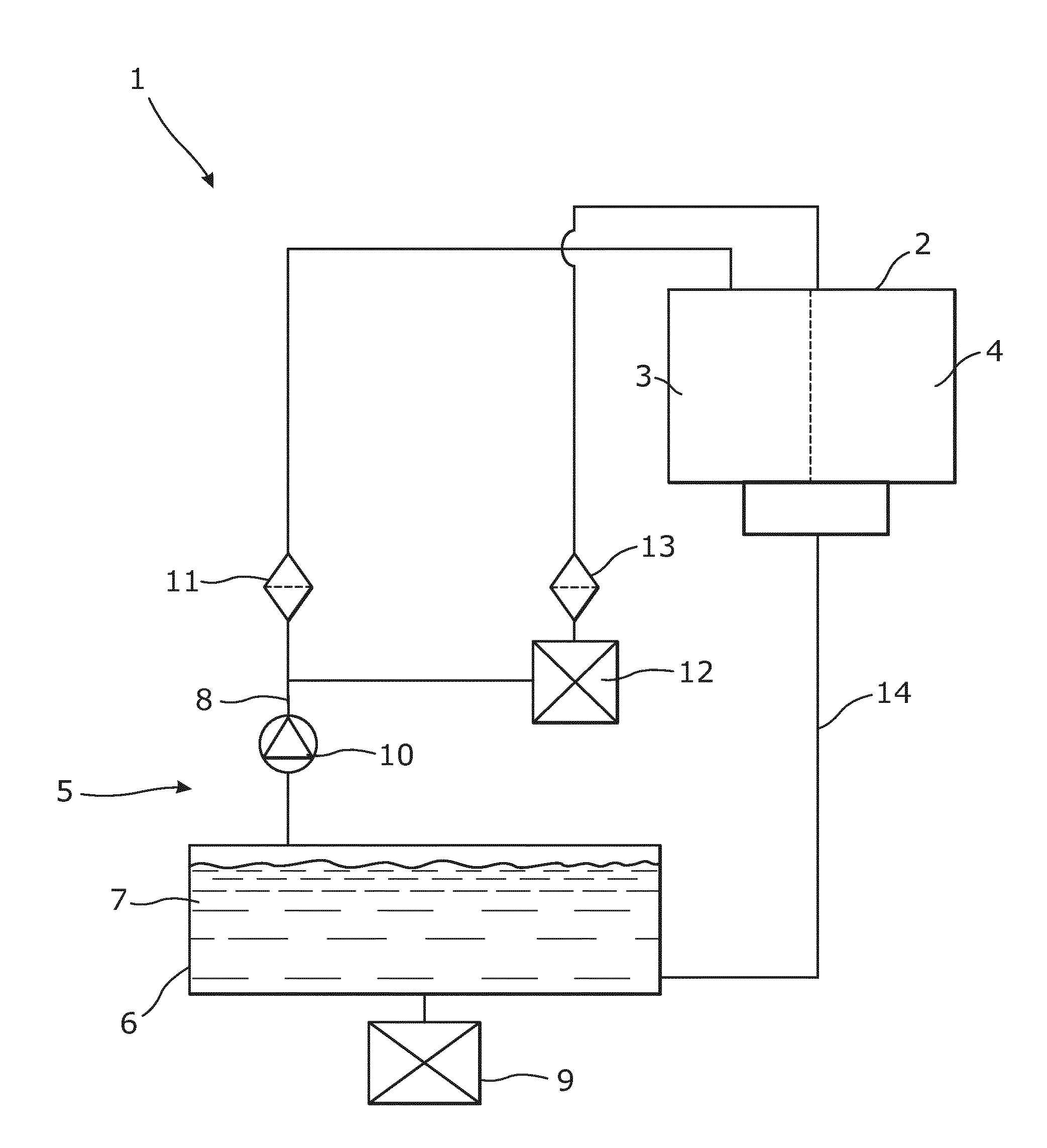
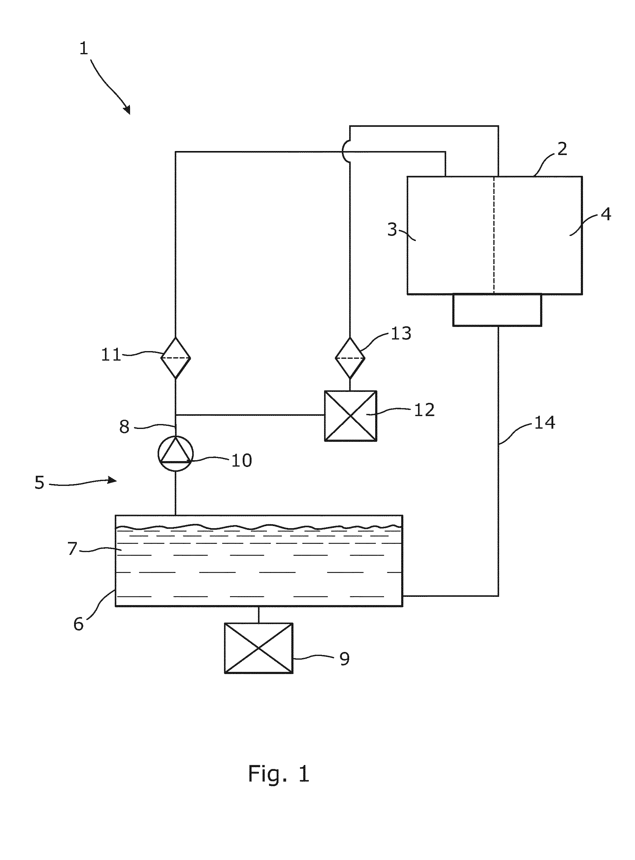
[0067]FIG. 1 shows a schematic diagram of a machine system 1 having a lubrication system according to the present invention.

[0068]The machine system 1 comprises a machine 2 having at least a first section 3 and a second section 4. The first section 3 has a first velocity, i.e. different machine components having working speeds / velocities, and the second section 4 has a second velocity, i.e. different machine components having working speeds / velocities. The second velocity is different from the first velocity. In FIG. 1, the two sections 3, 4 are separated by a dotted line.

[0069]Furthermore, a lubrication system 5 is arranged in connection with the machine system 1. In the embodiment shown in FIG. 1, the lubrication system 5 comprises one tank 6 having one lubricant 7, and the lubrication system 5 is connected to the first and second sections 3, 4 via a conduit system 8.

[0070]In connection with the tank 6, a heat exchanger 9 is arranged for changing the temperature of the lubricant 7...


PUM


Abstract

The present invention relates to a machine system comprising a machine having at least a first section and a second section, the first section having a first velocity and the second section having a second velocity, the second velocity being different from the first velocity, and a lubrication system comprising at least one tank having one lubricant, the lubrication system being connected to the first and second sections. Furthermore, the invention relates to a wind turbine comprising the machine system.

Description

FIELD OF THE INVENTION[0001]The present invention relates to a machine system comprising a machine having at least a first section and a second section, the first section having a first velocity and the second section having a second velocity, the second velocity being different from the first velocity, and a lubrication system comprising at least one tank having one lubricant, the lubrication system being connected to the first and second sections. Furthermore, the invention relates to a wind turbine comprising the machine system.[0002]The present invention also relates to a method for lubricating a machine system.BACKGROUND ART[0003]Machines having different moving parts need to be lubricated in order to function properly. Gearbox systems used for instance in connection with wind turbines are usually lubricated by one or more lubricants supplied to the different lubrication points at substantially the same temperature.[0004]With a typical gear ratio of >100 (and up to 150 in a ...

Claims


Application Information

Patent Timeline
IPC IPC(8): F16H57/04F01M5/00
CPCF16H57/0413F01M5/00F16H57/0436F01M5/001F01M5/002F01M5/005F05B2260/98
Inventor BAUM, JOCHENDEMTRODER, JENSRUSCHOFF, RALF
Owner VESTAS WIND SYST AS
Learn More