
Internal combustion engine and lubrication system thereof

An internal combustion engine, lubrication system technology, applied in the direction of engine lubrication, combustion engine, engine components, etc.

Active Publication Date: 2013-09-04
FORD GLOBAL TECH LLC
View PDF6 Cites 0 Cited by
  • Summary
  • Abstract
  • Description
  • Claims
  • Application Information

AI Technical Summary

Problems solved by technology

This has the disadvantage that the hood wiring of a motor vehicle will generally require higher hood wiring than would otherwise be required
However, it is not possible to use this small volume of oil in a normal sump, as this would lead to fill rate problems and potential internal combustion engine oil starvation

Method used


Image

  • Internal combustion engine and lubrication system thereof
  • Internal combustion engine and lubrication system thereof
  • Internal combustion engine and lubrication system thereof

Examples


Embodiment Construction

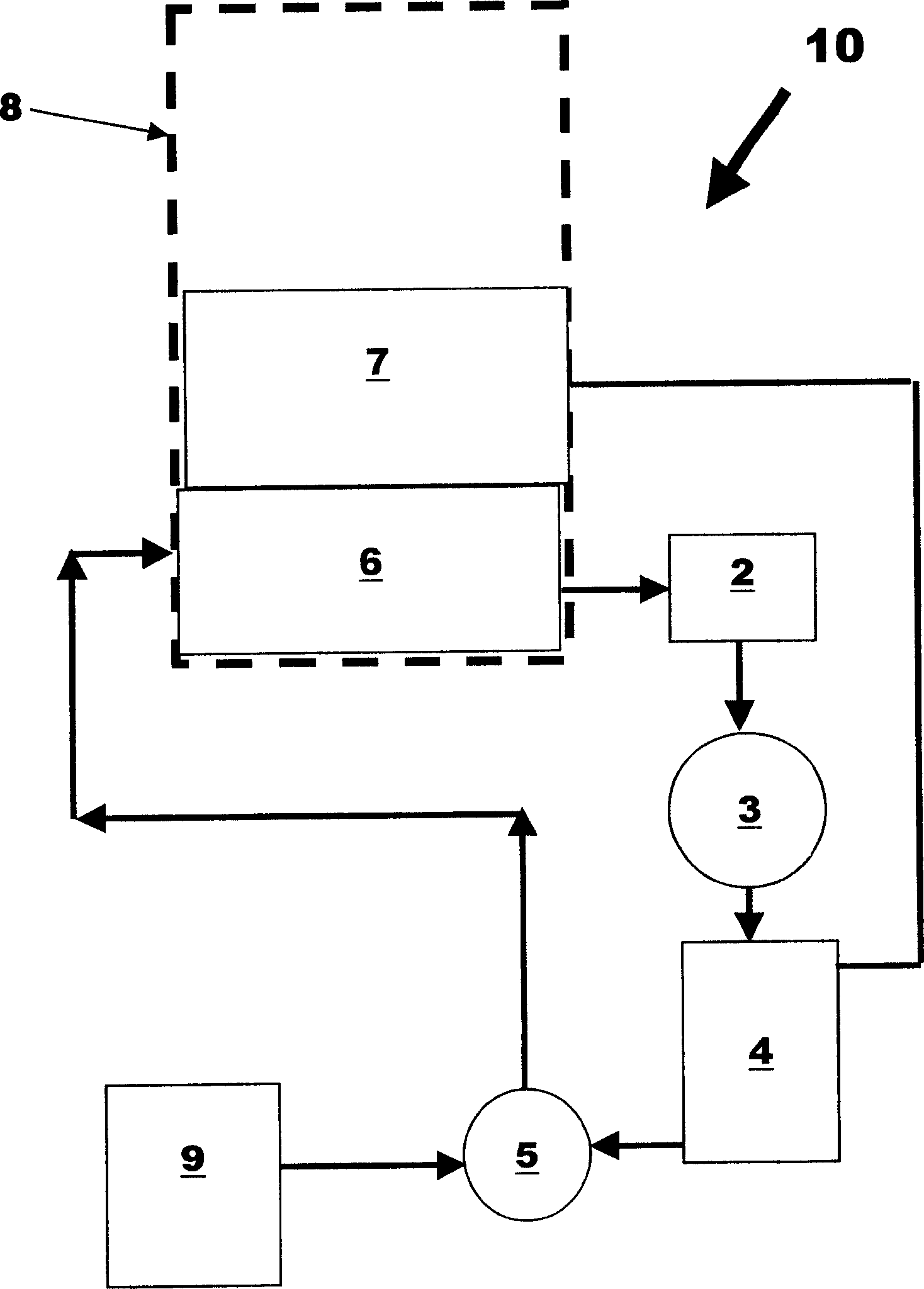
[0037] Special reference below figure 1 The invention is described, figure 1 A motor vehicle 10 is shown having an internal combustion engine 8 . Engine 8 includes a crankcase 7 and a main oil storage container or sump 6 .

[0038] The engine 8 is equipped with a lubrication system for lubricating not only the various moving parts of the engine 8 but also the turbocharger 3, which is operatively connected to the exhaust manifold (not shown) of the engine 8 to provide Improved internal combustion engine performance.

[0039] The lubrication system comprises: an oil pump 2 for pumping lubricant in the form of oil from the main oil reservoir 6 to the turbocharger 3 and in particular to the bearings of the turbocharger 3; the secondary oil reservoir 4 that receives the oil from the turbocharger bearings; and the engine-driven vacuum pump 5 for providing a partial vacuum within the secondary oil reservoir 4, thereby pushing the oil from the turbocharger bearings to the seconda...


PUM


Abstract

An internal combustion engine (8) is provided with a lubrication system for a turbocharger (3) fitted to the engine, the lubrication system comprising an oil pump (2) for pumping oil from a main oil reservoir (6) One or more bearings feeding the turbocharger (3), a secondary oil reservoir (4) for receiving oil from the turbocharger bearings, and a vacuum pump (5) for pushing oil from the turbocharger The oiler bearing flows into the secondary oil reservoir and pumps oil from the secondary oil reservoir back to the main oil reservoir. Another feature of the invention is that the vacuum pump (5) for pumping oil back from the secondary oil storage container can be used as a vacuum source for the vacuum operating system (9).

Description

technical field [0001] The present invention relates to the lubrication of internal combustion engines and, in particular, to the lubrication of turbochargers fitted to such engines. Background technique [0002] It is known that the performance of internal combustion engines can be improved by using exhaust-gas turbochargers. It is further known to provide such turbochargers with lubrication, wherein oil is fed from the engine to the turbocharger via an oil feed and returns by gravity to the sump of the engine. To prevent oil clogging in the drain line from such turbochargers, the turbocharger is typically mounted as high as possible to provide the longest possible drain line, and a generally vertical drain line is often used to assist in draining. This has the disadvantage that the hood wiring of a motor vehicle will generally require higher hood wiring than would otherwise be required. [0003] A blockage in the drain line from the turbocharger is a concern as it can le...

Claims


Application Information

Patent Timeline
Patent Type & Authority Patents(China)
IPC IPC(8): F01M1/02F01D25/18F01M9/10F02B37/007F02B39/14
CPCF01M9/108F02B37/007F02B39/14F01M11/04F02B37/00F16N7/40F16N31/00
Inventor 戴米安·米切尔·帕克鲁斯·玛蒂安德鲁·约翰·迈克法勒尼詹姆斯·玛蒂·奥特斯
Owner FORD GLOBAL TECH LLC
Learn More