
Devices Having an Integrated Computational Element and a Proximal Interferent Monitor and Methods for Determining a Characteristic of a Sample Therewith

a technology of proximal interference and computational elements, applied in the direction of optical radiation measurement, instruments, heat measurement, etc., can solve the problems of additional delays, high cost and complexity of spectroscopic instruments transitioning from the laboratory into the field or process environment, and affecting the quality of the sampl

Active Publication Date: 2013-10-31
HALLIBURTON ENERGY SERVICES INC
View PDF1 Cites 84 Cited by
  • Summary
  • Abstract
  • Description
  • Claims
  • Application Information

AI Technical Summary

Benefits of technology

The patent relates to devices and methods for using integrated computational elements to determine characteristics of a sample. The device includes a sample detection unit with an integrated computational element and a detector for receiving electromagnetic radiation that has interacted with the computational element and producing a sample signal. An interferent monitor produces an interferent signal associated with interfering substances or conditions. A signal processing unit converts the interferent signal into an interferent input form and combines it with the sample signal to determine the characteristics of the sample in real-time or near real-time. The technical effect is the ability to correct signals received from an integrated computational element in the presence of interfering substances or conditions, resulting in accurate and reliable detection of sample characteristics.

Problems solved by technology

Sample preparation steps can result in delays of hours to days when obtaining an analysis.
Furthermore, there can be additional delays associated with transporting the sample to a laboratory equipped to carry out the analysis.
Although spectroscopic techniques can, at least in principle, be conducted at a job site in real-time or near real-time, the transitioning of spectroscopic instruments from the laboratory into a field or process environment can be expensive and complex.
For example, conditions such as inconsistent temperature, humidity, and vibration can be commonly encountered during field or process use, and they can be difficult to compensate for with conventional spectroscopic instruments.
At a minimum, these conditions and others can affect the calibration and durability of many types of spectroscopic instruments.
Further, field personnel may not have the training needed to satisfactorily carry out a spectroscopic analysis and take appropriate action in response.
Further, optical computing devices are generally operationally simple and rugged.
Outside this calibration range, an interferent substance or condition may alter the response of the optical computing device such that its output is no longer representative of a sample's characteristic, for example.
Interferent substances or conditions may undesirably interact with any component of an optical computing device, including its integrated computational element and / or electronic components associated therewith, to alter its response.
In other cases, a sufficient amount of an interferent substance within or near a sample may change or block a spectral absorbance related to a characteristic of interest.
Any of these events may result in a breadth of outcomes, ranging from questionable data integrity to complete data unintelligibility.
In the case of certain field and process operations, questionable and / or lost data can present serious financial consequences and impact the ability to perform a job or evaluate the effectiveness of a job.

Method used


Image

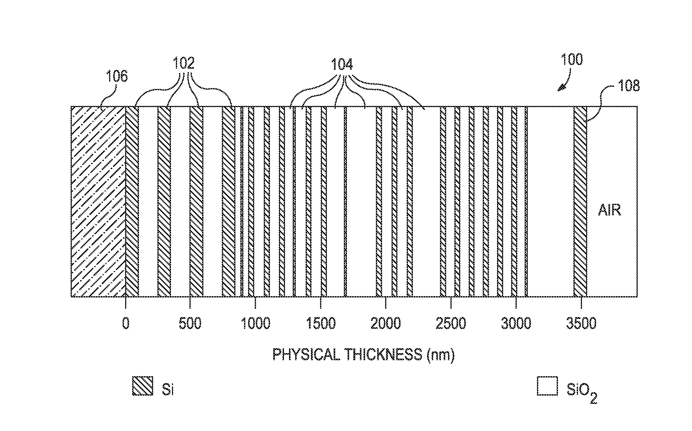
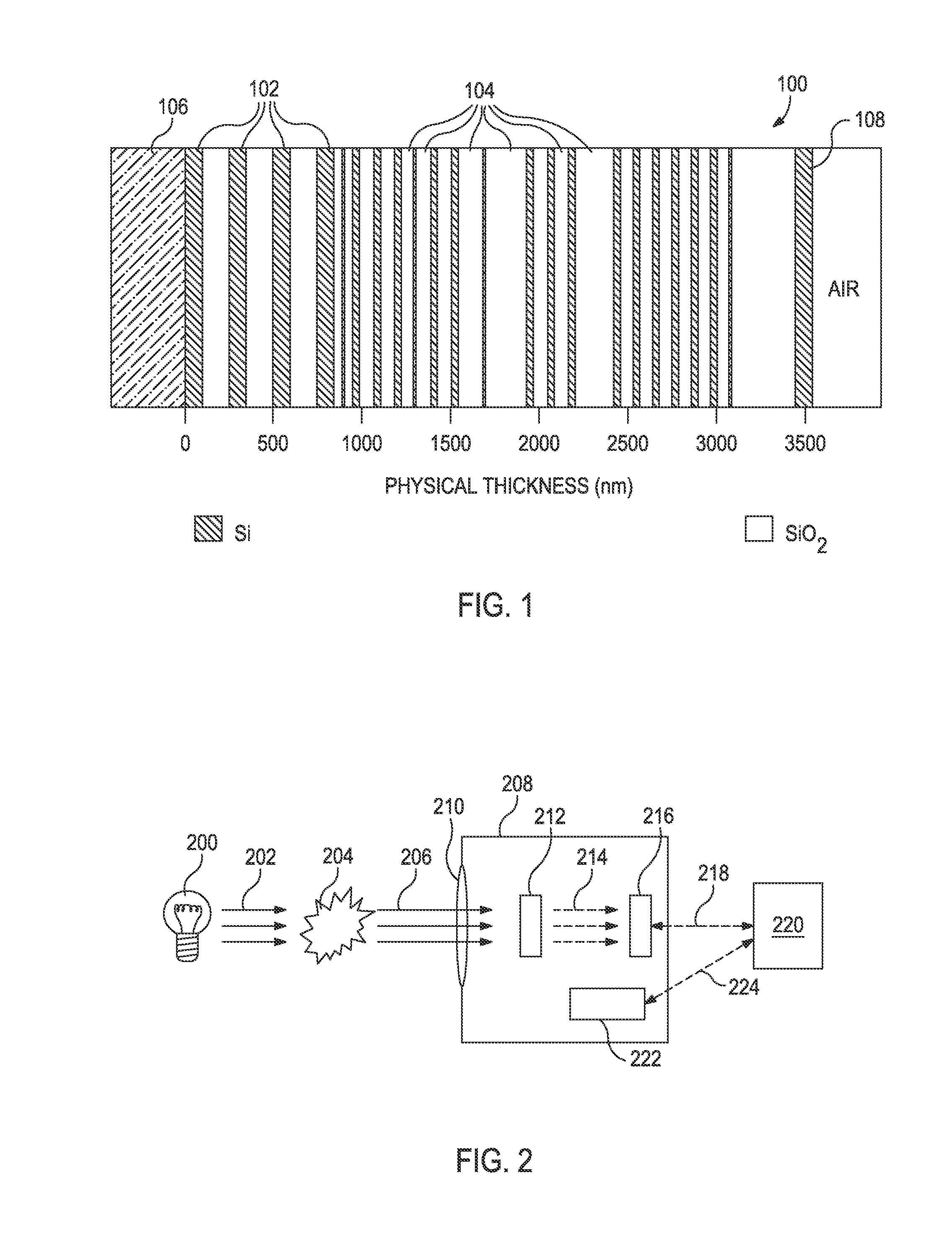
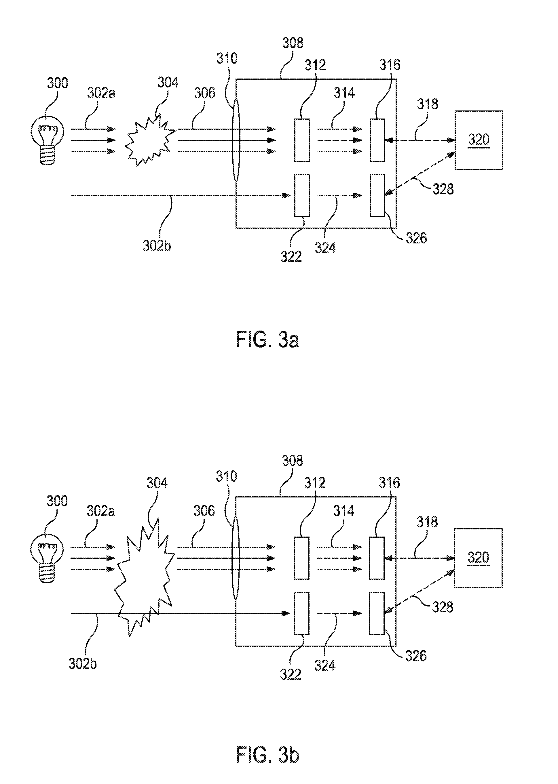
  • Devices Having an Integrated Computational Element and a Proximal Interferent Monitor and Methods for Determining a Characteristic of a Sample Therewith
  • Devices Having an Integrated Computational Element and a Proximal Interferent Monitor and Methods for Determining a Characteristic of a Sample Therewith
  • Devices Having an Integrated Computational Element and a Proximal Interferent Monitor and Methods for Determining a Characteristic of a Sample Therewith

Examples


Embodiment Construction

[0021]The present disclosure relates to devices and methods for determining a characteristic of a sample using an integrated computational element, and, more specifically, to devices and methods that can correct a signal received from an integrated computational element in the presence of one or more interferent substances or interferent conditions.

[0022]Although the output simplicity of optical computing devices (i.e., a real number) is one of their strengths, this feature has heretofore limited one's ability to evaluate and correct the output when one or more interferents are present. As used herein, the term “interferent” refers to a substance or condition that changes the output of an optical computing device when evaluating a characteristic of interest in a sample. As used herein, the term “interferent substance” refers to a material that, when present, alters the sample signal associated with an optical computing device. As used herein, the term “interferent condition” refers ...


PUM

PropertyMeasurementUnit
electromagnetic radiationaaaaaaaaaa
real-timeaaaaaaaaaa
temperatureaaaaaaaaaa

Abstract

The output of optical computing devices containing an integrated computational element can be corrected when an interferent substance or condition is present. The devices may comprise an optional electromagnetic radiation source; a sample detection unit comprising an integrated computational element and a detector configured to receive electromagnetic radiation that has optically interacted with the integrated computational element and produce a sample signal associated therewith; an interferent monitor located proximal to the sample detection unit, the interferent monitor being configured to produce an interferent signal associated with an interferent substance; and a signal processing unit operable to convert the interferent signal into an interferent input form suitable for being computationally combined with the sample signal, the signal processing unit being further operable to computationally combine the sample signal and the interferent input form to determine a characteristic of a sample in real-time or near real-time.

Description

BACKGROUND[0001]The present disclosure relates to devices and methods for determining a characteristic of a sample using an integrated computational element, and, more specifically, to devices and methods that can correct a signal received from an integrated computational element in the presence of one or more interferent substances or interferent conditions.[0002]Spectroscopic techniques for measuring various characteristics of materials are well known and routinely used under laboratory conditions. In cases where there is not extensive sample matrix interference, spectroscopic techniques can sometimes be carried out without using an involved sample preparation. It is more common, however, to carry out various sample preparation procedures before conducting the analysis. Reasons for conducting sample preparation procedures before carrying out an analysis can include, for example, removing interferent substances from the sample, converting an analyte of interest into a chemical form...

Claims


Application Information

Patent Timeline
Patent Type & Authority Applications(United States)
IPC IPC(8): G01N21/17G01K13/00
CPCG01N21/17G01K13/00G01N21/274G06E3/001G01N2201/1211G01N2201/1214G01N2201/1215
Inventor FREESE, ROBERTJONES, CHRISTOPHER MICHAELPERKINS, DAVIDSIMCOCK, MICHAELSOLTMANN, BILL
Owner HALLIBURTON ENERGY SERVICES INC
Learn More