
System and method for cooling a gas turbine with an exhaust gas provided by the gas turbine

a technology of gas turbine and exhaust gas, which is applied in the direction of engines, mechanical equipment, machines/engines, etc., can solve the problems of limiting the mechanical life of the gas turbine, generating high temperatures, and generating high temperatures

Active Publication Date: 2013-10-31
EXXONMOBIL UPSTREAM RES CO +1
View PDF7 Cites 89 Cited by
  • Summary
  • Abstract
  • Description
  • Claims
  • Application Information

AI Technical Summary

Benefits of technology

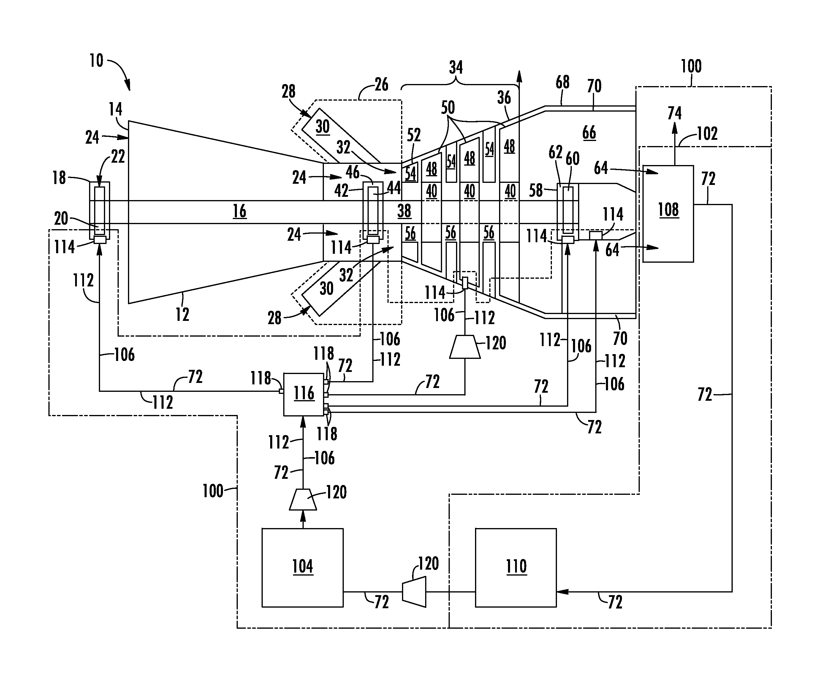
This patent describes a system for cooling a gas turbine using exhaust gas from the turbine. The system includes an exhaust gas recirculation system with an exhaust gas scrubber, a moisture separator, and a cooling circuit that connects to the turbine. This system helps to reduce emissions and improve efficiency of the gas turbine.

Problems solved by technology

In addition, various components of a gas turbine, such as rotor support bearings, generate high temperatures due to friction forces and / or loads placed upon the gas turbine.
As a result, high thermal stresses may significantly limit the mechanical life of the gas turbine.
Although current methods are generally effective, there is a growing concern over the long-term effects of Nitrous Oxides (hereinafter NOx), Carbon Dioxide (hereinafter “CO2”), Carbon Monoxide (hereinafter CO) and Sulfur Oxides (hereinafter SOx) emissions on the environment.
However, impurities and / or moisture within the exhaust gas prevent utilizing a simple re-circulating loop to reduce the CO2, SOx, and NOx.
As a result, turbine fouling, corrosion, and accelerated wear of internal gas turbine components would result from introducing the exhaust gas directly to the gas turbine for combustion and / or for use as a cooling medium.
In addition, significant amounts of condensable vapors exist in the exhaust gas stream.
Left untreated, these constituents will accelerate corrosion and the fouling of the internal components, if allowed to enter the gas turbine through one or more cooling circuits of the gas turbine.

Method used


Image

  • System and method for cooling a gas turbine with an exhaust gas provided by the gas turbine
  • System and method for cooling a gas turbine with an exhaust gas provided by the gas turbine
  • System and method for cooling a gas turbine with an exhaust gas provided by the gas turbine

Examples


Embodiment Construction

[0013]Reference will now be made in detail to present embodiments of the invention; one or more examples of which are illustrated in the accompanying drawings. The detailed description uses numerical and letter designations to refer to features in the drawings. Like or similar designations in the drawings and description have been used to refer to like or similar parts of the invention.

[0014]Each example is provided by way of explanation of the invention, not limitation of the invention. In fact, it will be apparent to those skilled in the art that modifications and variations can be made in the present invention without departing from the scope or spirit thereof. For instance, features illustrated or described as part of one embodiment may be used on another embodiment to yield a still further embodiment. Thus, it is intended that the present invention covers such modifications and variations as come within the scope of the appended claims and their equivalents.

[0015]Certain termin...


PUM


Abstract

A system for cooling a gas turbine with an exhaust gas provided by the gas turbine generally includes an exhaust gas recirculation system including an exhaust gas scrubber. The exhaust gas recirculation system is disposed downstream from the gas turbine and may receive at least a portion of the exhaust gas provided by the gas turbine. The system may also include a moisture separator located downstream from the exhaust gas recirculation system, and a cooling circuit configured to connect to one or more cooling circuit inlets. The one or more cooling circuit inlets may provide fluid communication between the cooling circuit and the gas turbine.

Description

FIELD OF THE INVENTION[0001]The present invention relates to a system and a method for cooling a gas turbine with an exhaust gas provided by the gas turbine.BACKGROUND OF THE INVENTION[0002]Modern gas turbines generally operate at extremely high temperatures. In addition, various components of a gas turbine, such as rotor support bearings, generate high temperatures due to friction forces and / or loads placed upon the gas turbine. As a result, high thermal stresses may significantly limit the mechanical life of the gas turbine. Therefore, it is necessary to provide a cooling medium to the gas turbine to prevent overheating and premature failure of the various components. Current methods for cooling and / or sealing the gas turbine include flowing a working fluid, such as compressed air and / or steam, to the various components of the gas turbine. Although current methods are generally effective, there is a growing concern over the long-term effects of Nitrous Oxides (hereinafter NOx), Ca...

Claims


Application Information

Patent Timeline
IPC IPC(8): F02C3/34F02C7/141F02C3/04
CPCF02C7/18F02C3/34F02C7/141
Inventor KOLVICK, SANDRA BEVERLY
Owner EXXONMOBIL UPSTREAM RES CO
Learn More