
Electrically conductive member, process cartridge and electrophotographic apparatus

a technology of electrophotography and electrically conductive components, which is applied in the direction of electrographic process apparatus, coatings, instruments, etc., can solve the problems of difficult uniform dispersion of electron conducting agents in binder resin, and difficult local uniform dispersion of electrically conductive layers. achieve the effect of stably forming high-grade electrophotographic images and not easily causing any bleeding of electrically conductive layers

Inactive Publication Date:
View PDF2 Cites 41 Cited by
  • Summary
  • Abstract
  • Description
  • Claims
  • Application Information

AI Technical Summary

Benefits of technology

The present invention is about improving the electrically conductive member used in electrophotography. The invention aims to create a conductive member that is resistant to changes in environmental factors and prevents bleeding of the conducting agent over a long period of contact with other members. This results in stable formation of high-quality electrophotographic images. The invention also provides a process cartridge and an elephotographic apparatus to achieve this improvement.

Problems solved by technology

However, it is difficult for the electron conducting agent to be uniformly dispersed in a binder resin, and the electron conducting agent tends to aggregate in the electrically conductive layer.
Hence, there is a possibility that the electrically conductive layer comes to be locally non-uniform in electrical resistance value.
On the other hand, in an electrically conductive layer having been made electrically conductive by the ion conducting agent, the ion conducting agent is uniformly dispersed in the binder resin compared with the electron conducting agent, and hence the electrically conductive layer can not easily come to be locally non-uniform in electrical resistance.
However, the ion conducting agent is, for its ionic conduction performance, susceptible to the water content in the binder resin in a service environment.
That is, it has a problem that its electrical resistance value has a large environmental dependence.
Further, where an electrically conductive member having the electrically conductive layer having been made electrically conductive by the ion conducting agent is left to stand over a long period of time in the state it is kept in contact with other member, the ion conducting agent may soak out of the electrically conductive layer to its surface (hereinafter often “bleeding”).

Method used


Image

  • Electrically conductive member, process cartridge and electrophotographic apparatus
  • Electrically conductive member, process cartridge and electrophotographic apparatus
  • Electrically conductive member, process cartridge and electrophotographic apparatus

Examples


example 1

[0134]1. Preparation of Electrically Conductive Layer Coating Solution:

[0135]0.735 g (0.988 mmol) of polyethylene glycol diglycidyl ether (mass-average molecular weight: 744) and 0.057 g (0.384 mmol) of ethylene glycol bis(2-aminoethyl) ether as compounds having the structure represented by the formula (1)-1, 1.169 g (0.835 mmol) of amine-terminated modified NBR (trade name: ATBN 1300X35; available from Ube Industries, Ltd.) as a compound having the structure represented by the formula (2)-1 and 0.039 g (2 parts by mass based on 100 parts by mass of the binder resin) of the ion conducting agent a were dissolved in isopropyl alcohol (IPA) to prepare a “coating solution 1” having a solid content of 27% by mass. Incidentally, n1 of the formula (1)-1 was 13, and [m1:p1] of the formula (2)-1 was 74:26.

[0136]2. Coating of Electrically Conductive Layer Coating Solution:

[0137]The elastic roller A was, with its lengthwise direction set in the vertical direction, dipped in the coating solutio...

examples 2 to 47

[0147]Conductive rollers 2 to 47 were produced, and evaluated as charging rollers, in the same way as Example 1 except that, as raw materials for the electrically conductive layer, stated materials of those shown in Table 4 were used and the amounts of the materials used were changed to values shown in Tables 5-1 to 5-4. The results of evaluation are shown in Tables 7-1 to 7-5.

example 48

[0148]An electrically conductive member 48 was produced, and evaluated as a charging roller, in the same way as Example 1 except that the elastic roller A was changed for the elastic roller B. The results of evaluation are shown in Table 7-5.


PUM


Abstract

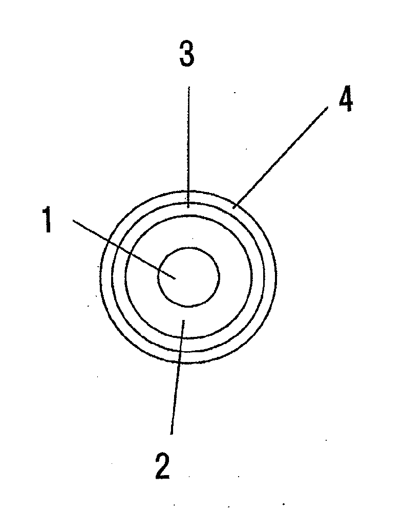
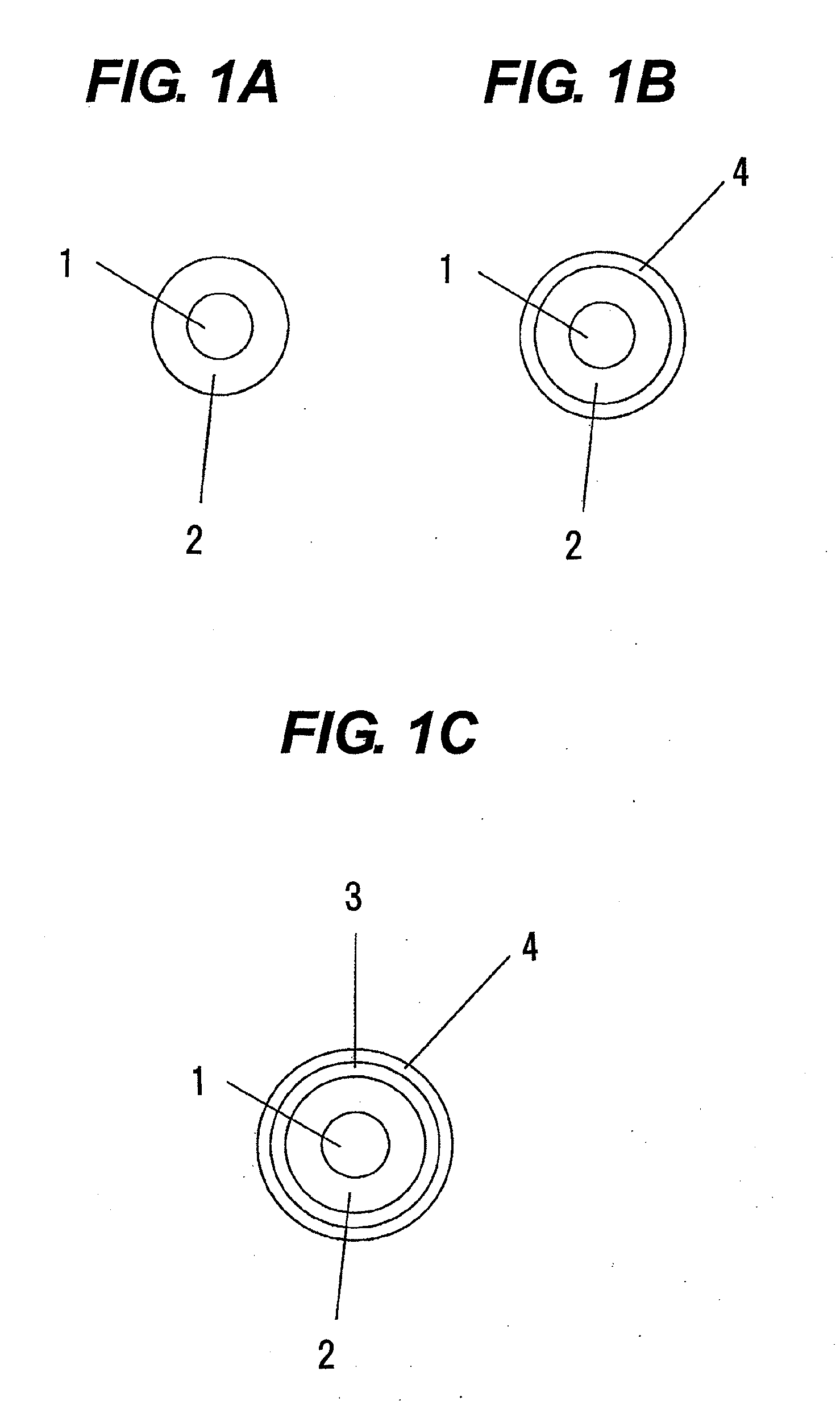
An electrically conductive member for electrophotography is provided which has an electrically conductive mandrel and an electrically conductive layer on the peripheral surface of the mandrel; the electrically conductive layer containing a binder resin having as an ion exchange group a sulfo group or a quaternary ammonium salt group in the molecule and an ion with a polarity opposite to that of the ion exchange group; the binder resin further having any structure selected from the group consisting of structures represented by formulas (1)-1 to (1)-3, and any structure selected from the group consisting of structures represented by formulas (2)-1 and (2)-2, and having a molecular structure that prevents any matrix-domain structure from being formed in the electrically conductive layer.

Description

CROSS-REFERENCE TO RELATED APPLICATIONS[0001]This application is a continuation of International Application No. PCT / JP2012 / 008052, filed Dec. 17, 2012, which is claims the benefit of Japanese Patent Application No. 2011-284451, filed Dec. 26, 2011.BACKGROUND OF THE INVENTION[0002]1. Field of the Invention[0003]The present invention relates to an electrically conductive member, a process cartridge and an electrophotographic apparatus.[0004]2. Description of the Related Art[0005]In electrophotographic image forming apparatus, conductive members are used in various ways, e.g., as a charging roller, a developing roller and a transfer roller. It is preferable for such conductive members to have electrical resistance value in the range of from 103Ω to 1010Ω. Hence, for electrically conductive layers the conductive members have, their conductivity is regulated with a conducting agent. Here, the conducting agent is roughly classified into an electron conducting agent as typified by carbon ...

Claims


Application Information

Patent Timeline
Patent Type & Authority Applications(United States)
IPC IPC(8): B05C1/08
CPCG03G15/751G03G2215/00957
Inventor WATANABE, MASAHIROYAMAUCHI, KAZUHIRONISHIOKA, SATORUKIKUCHI, YUICHI
Learn More