Battery unit connection structure of electric vehicle

a technology of electric vehicles and battery units, which is applied in the direction of batteries, cell components, cycle equipments, etc., can solve the problems of large load acting on the joint of the connectors, and achieve the effects of accurate and easy connection, and improved workability in attaching the battery uni

Inactive Publication Date: 2013-10-24
HONDA MOTOR CO LTD
View PDF1 Cites 12 Cited by
  • Summary
  • Abstract
  • Description
  • Claims
  • Application Information

AI Technical Summary

Benefits of technology

The patent aims to improve the attachment of battery units in electric vehicles by making the connection between the battery side connector and the vehicle body side connector easier and more reliable. This makes it easier for users to install and use the battery unit.

Problems solved by technology

This requires careful work because an attempt to turn the battery unit while the battery side connector and the vehicle body side connector are not properly fit causes a large load to act on a joint of the connectors.

Method used


Image

  • Battery unit connection structure of electric vehicle
  • Battery unit connection structure of electric vehicle
  • Battery unit connection structure of electric vehicle

Examples


Embodiment Construction

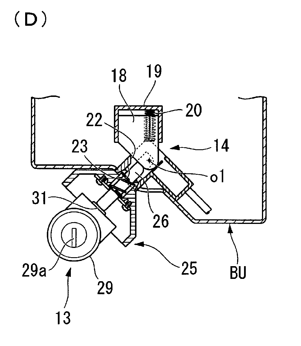
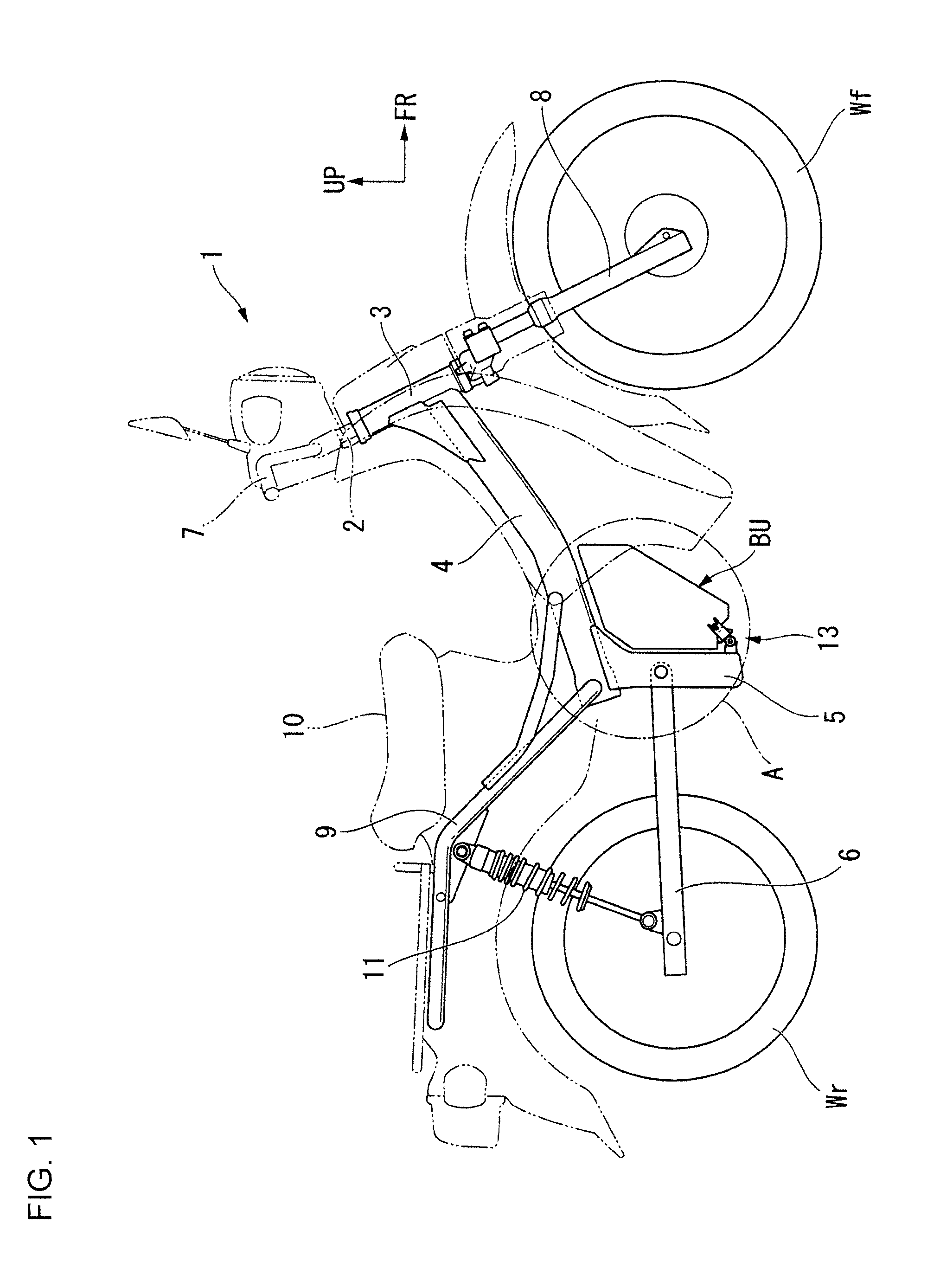
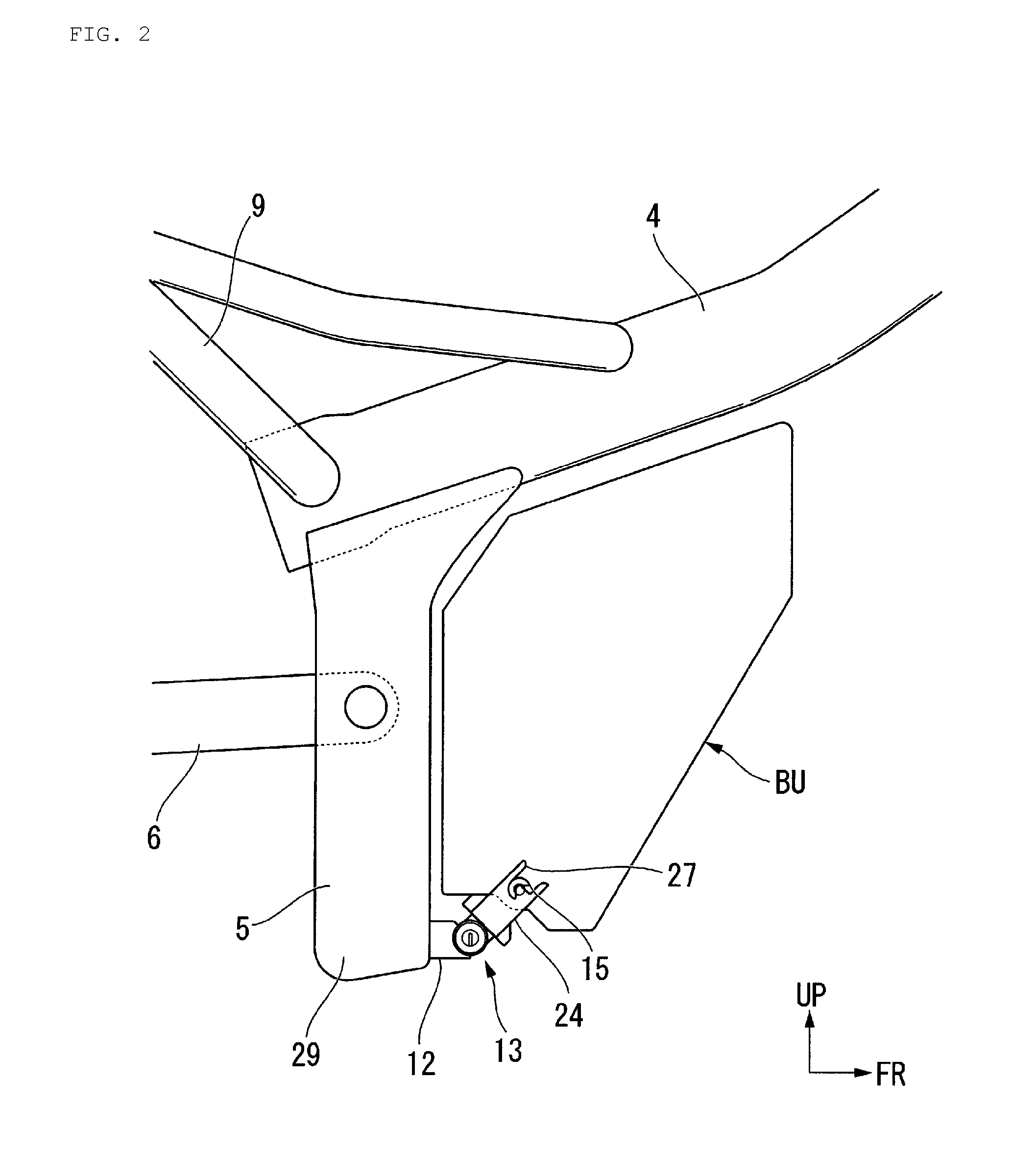
[0036]Hereinafter, a description is given of embodiments of the present invention with reference to the drawings. Note that front-rear, left-right and other directions in the following description are the same as the directions of a vehicle if not stated otherwise. In addition, in the drawings, an arrow FR indicates the front of the vehicle, an arrow LH indicates the left side of the vehicle, and an arrow UP indicates the upper part of the vehicle.

[0037]FIG. 1 is a view showing a side of an electric motorcycle 1 which is one form of an electric vehicle.

[0038]The motorcycle 1 includes a main frame 4 joined to a head pipe 3 which turnably holds a handle post 2. The main frame 4 extends obliquely downward toward the rear from the head pipe 3, and a center frame 5 is joined integrally with a lower part of the rear end portion of the main frame 4. A battery unit BU being a power supply source of the vehicle is detachably and attachably installed in front of the center frame 5. In additio...


PUM

PropertyMeasurementUnit
angleaaaaaaaaaa
angleaaaaaaaaaa
forceaaaaaaaaaa

Abstract

A vehicle can have a battery unit which includes paired supporting shafts protruding in opposite directions. A battery side connector can be supported coaxially with the supporting shafts in a turnable manner. The direction in which the battery side connector is fitted and connected is the direction orthogonal to the supporting shafts. A battery holding block includes paired engaging recessed portions and a vehicle body side connector. The supporting shafts of the battery unit are inserted into the engaging recessed portions from a direction approximately orthogonal to the shaft. The battery side connector is fitted and connected to the vehicle body side connector. The battery unit is operated to turn around the supporting shaft to a position where the battery unit is fixed with the battery holding block.

Description

BACKGROUND[0001]1. Field[0002]The present invention relates to a battery unit connection structure of an electric vehicle equipped with a detachable / attachable battery unit as a power supply source.[0003]2. Description of the Related Art[0004]There is known an electric vehicle such as a two-wheeled electric vehicle, in which a battery unit is detachably attached to a battery holding portion of a vehicle body (see, for example, Japanese Patent Publication No. 2008-062814 (Patent Document 1)).[0005]In a battery unit connection structure of an electric vehicle described in Patent Document 1, a battery holding portion is provided at a base portion of a seat post supporting a seat. A battery unit is assembled in an inclined posture to the battery holding portion, and then turned so that the battery unit is positioned along the seat post.[0006]To be specific, in the battery unit connection structure of an electric vehicle, paired supporting shafts projecting toward opposite directions are...

Claims


Application Information

Patent Timeline
Patent Type & Authority Applications(United States)
IPC IPC(8): H01M2/10H01M50/244H01M50/249H01M50/264
CPCH01M2/1083H01M2220/20B60L2200/12Y02T10/7072B60L50/20B60L53/80B60L50/66B62K2202/00B62K2204/00Y02T10/70Y02E60/10B62J43/16B62J43/20H01M50/249H01M50/264H01M50/244Y02T90/14Y02T90/12
Inventor KAWATANI, SHINJI
Owner HONDA MOTOR CO LTD
Why Eureka
Try Eureka