
Device and method for deghosting variable depth streamer data

a streamer data and variable depth technology, applied in the direction of measuring devices, scientific instruments, instruments, etc., can solve the problems of limited land-based production fields, insufficient accuracy, and high cost of offshore drilling and drilling

Active Publication Date: 2013-10-24
CGG SERVICES SAS
View PDF1 Cites 32 Cited by
  • Summary
  • Abstract
  • Description
  • Claims
  • Application Information

AI Technical Summary

Benefits of technology

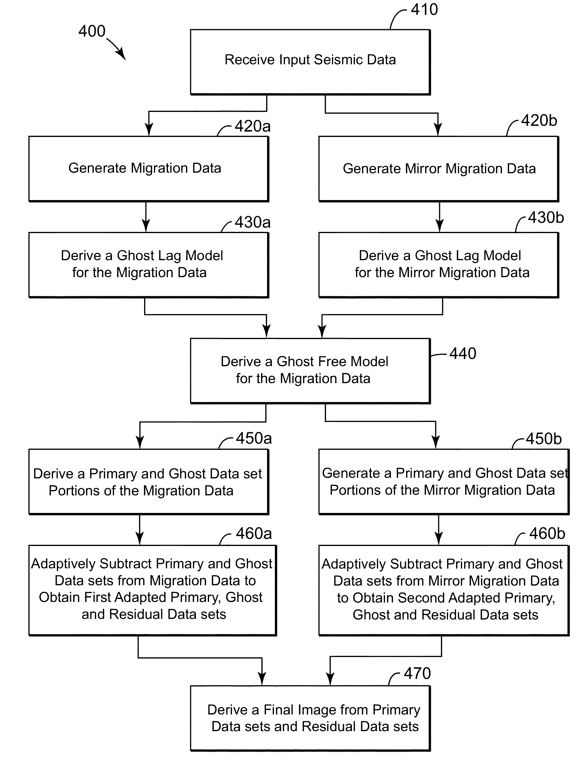
The patent describes a method for improving the image of underwater geological structures using seismic data. The method involves receiving the seismic data, generating migration data and mirror migration data, and deriving a ghost free model based on the migration data. Using this ghost free model, a final image of the subsurface can be obtained. The method also involves solving an equation and using a linear operator to incorporate the first and second ghost lag models. The technical effect is to improve the accuracy and quality of seismic images in a way that takes into account the impact of ghosts, which are signals that can interfere with the data.

Problems solved by technology

However, the availability of land based production fields is limited.
Offshore drilling is an expensive process.
While this profile does not provide an accurate location for oil and gas, it suggests, to those trained in the field, the presence or absence of oil and / or gas.
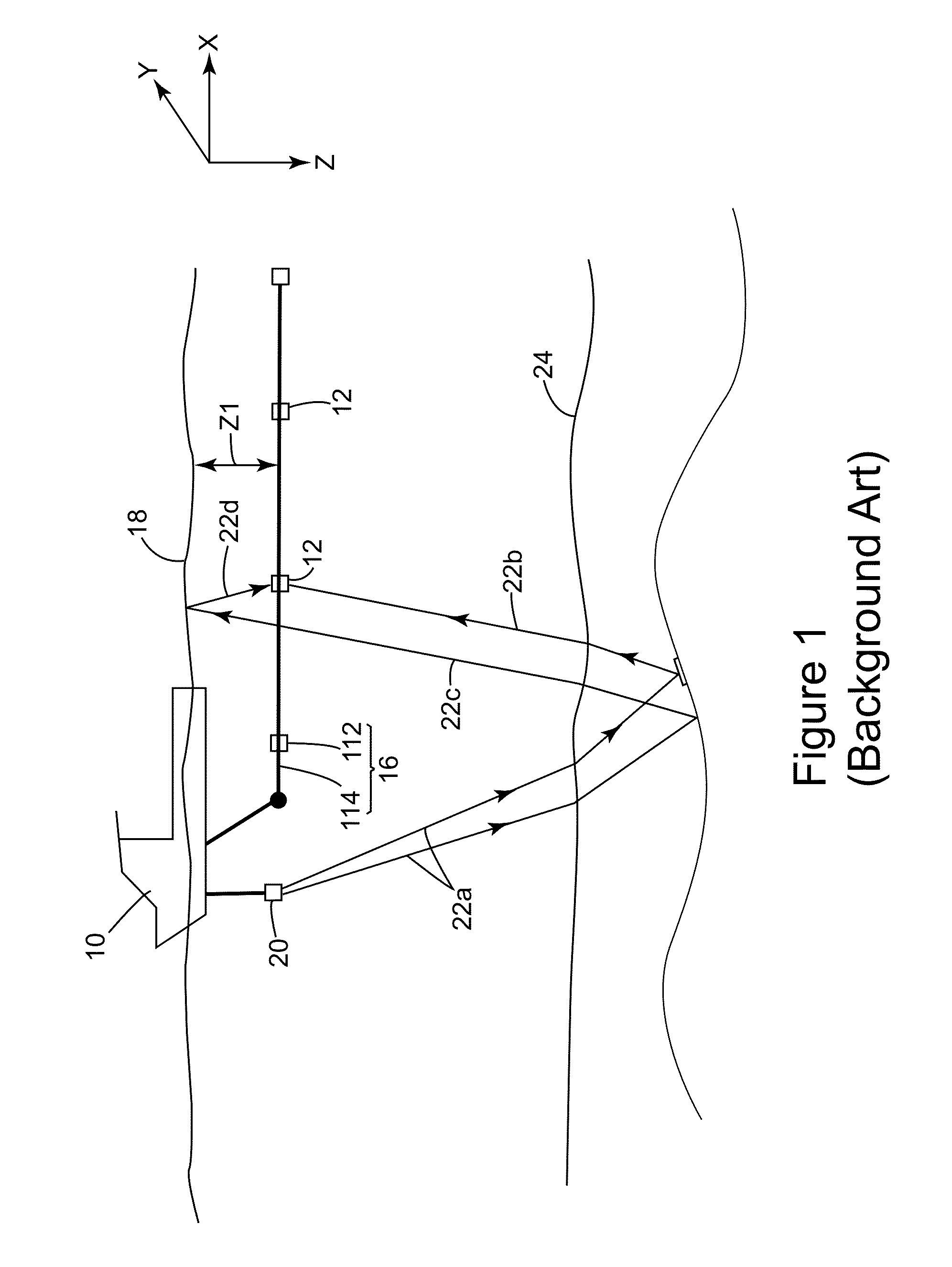
In essence, interference between primary and ghost arrivals causes notches, or gaps, in the frequency content recorded by the detectors.
However, the ghosts disturb the accuracy of the final image of the subsurface and, for at least this reason, various methods exist for removing the ghosts, i.e., deghosting, from the results of a seismic analysis.
Such procedures, however, cannot be generalized to three dimensions.
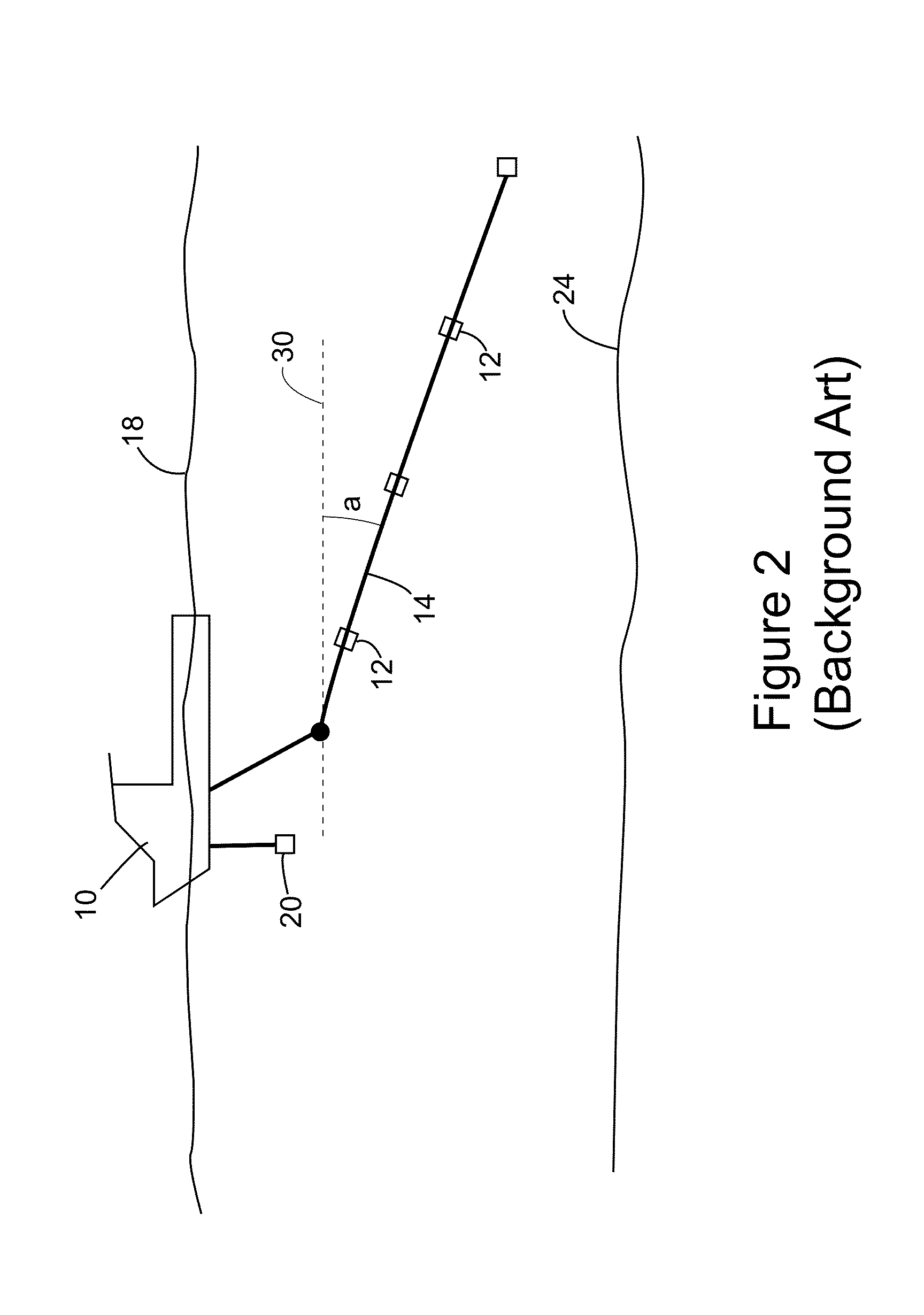
Thus, the above-discussed methods are not appropriate for seismic data collected with streamers having a curved profile as illustrated in FIG. 3.

Method used


Image

  • Device and method for deghosting variable depth streamer data
  • Device and method for deghosting variable depth streamer data
  • Device and method for deghosting variable depth streamer data

Examples


Embodiment Construction

[0027]The following description of the exemplary embodiments refers to the accompanying drawings. The same reference numbers in different drawings identify the same or similar elements. The following detailed description does not limit the invention. Instead, the scope of the invention is defined by the appended claims. The following embodiments are discussed, for simplicity, with regard to a two-dimensional (2D) wave-field propagation. However, the embodiments to be discussed next are not limited to 2D wave-fields, but may be also applied to 3D wave-fields.

[0028]Reference throughout the specification to “one embodiment” or “an embodiment” means that a particular feature, structure or characteristic described in connection with an embodiment is included in at least one embodiment of the subject matter disclosed. Thus, the appearance of the phrases “in one embodiment” or “in an embodiment” in various places throughout the specification is not necessarily referring to the same embodim...


PUM


Abstract

Computing device, computer instructions and method for deghosting seismic data related to a subsurface of a body of water. The method may include receiving input seismic data recorded by seismic receivers that located at different depths (zr), generating migration data (du) and mirror migration data (dd) from the input seismic data, deriving a ghost free model (m) based on simultaneously using the migration data (du) and mirror migration data (dd), generating primary (p) and ghost (g) datasets based on the ghost free model (m), simultaneously adaptively subtracting the primary (p) and ghost (g) datasets from the migration data (du) to provide adapted primary (p′1 and p′2) and adapted residual (r′1 and r′2) datasets and generating a final image (f) of the subsurface based on the adapted primary (p′1 and p′2) and the adapted residual (r′1 and r′2) datasets.

Description

CROSS-REFERENCE TO RELATED APPLICATIONS[0001]The present application claims the benefit of priority under 35 U.S.C. §119(e) to U.S. Provisional Application No. 61 / 635,489 filed on Apr. 19, 2012. The entire content of the above document is hereby incorporated by reference into the present application.BACKGROUND[0002]1. Technical Field[0003]Embodiments of the subject matter disclosed herein generally relate to methods and systems and, more particularly, to mechanisms and techniques for deghosting seismic data collected with one or more streamers having variable depths.[0004]2. Discussion of the Background[0005]Recently, interest in developing new oil and gas production fields has dramatically increased. However, the availability of land based production fields is limited. Thus, the industry has now extended drilling to offshore locations, which appear to hold a vast amount of fossil fuel. Offshore drilling is an expensive process. Thus, those engaged in such a costly undertaking inves...

Claims


Application Information

Patent Timeline
Patent Type & Authority Applications(United States)
IPC IPC(8): G01V1/38
CPCG01V1/38G01V1/364G01V2210/56G01V1/362
Inventor POOLE, GORDON
Owner CGG SERVICES SAS
Learn More