
Dynamic drive of switching transistor of switching power converter

a technology of switching power converter and switching transistor, which is applied in the direction of pulse technique, process and machine control, instruments, etc., can solve the problems of long turn-off time and unsuitable application of bjt, and achieve the reduction of the physical size of the switching power converter, the overall cost, and the effect of reducing the physical siz

Active Publication Date: 2013-10-24
DIALOG SEMICONDUCTOR INC
View PDF9 Cites 8 Cited by
  • Summary
  • Abstract
  • Description
  • Claims
  • Application Information

AI Technical Summary

Benefits of technology

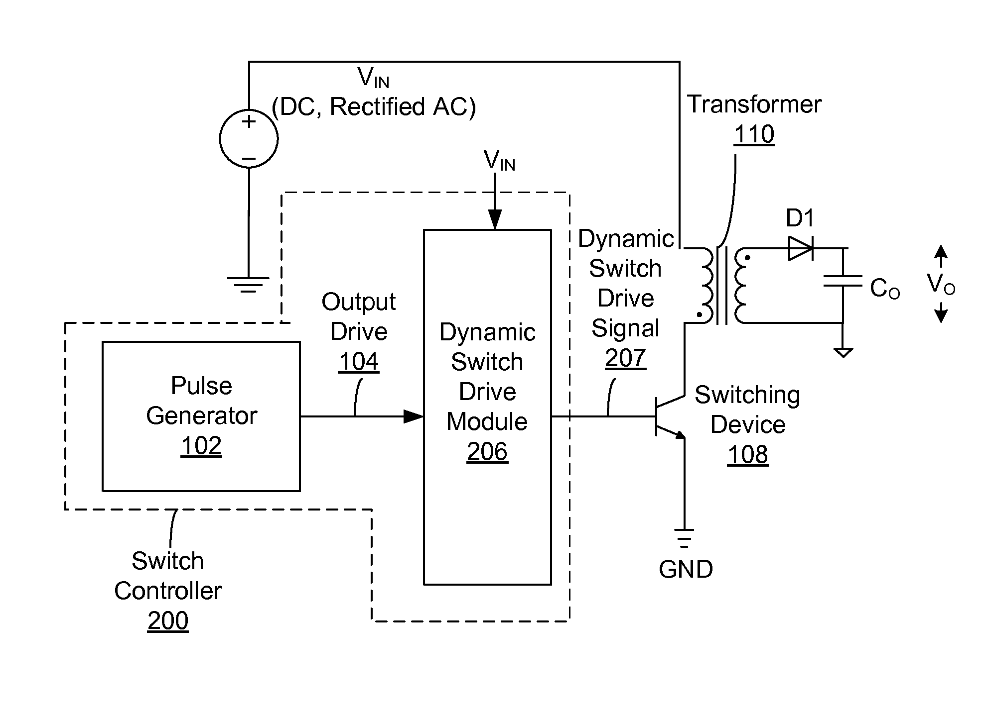
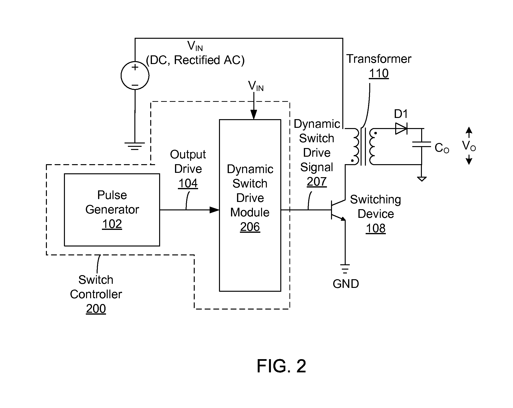
The present invention is about a circuit that allows for dynamic control of the driver of a switching power converter. This means that the circuit can adjust the way it controls the switching device based on the operating load or line conditions. This results in better performance of the switch and reduces the number of components, cost, and space required for the switching power converter. The circuit can also adjust the amplitude and duration of the driving signal, which makes it easier to achieve optimal performance of the switching device.

Problems solved by technology

However, when the switching device is a BJT 108 as shown in FIG. 1, it is undesirable to apply the +Vcc directly to the base of the BJT 108, since the BJT 108 is a current-drive device.
The BJT has long turn-off time due to its long storage time.

Method used


Image

  • Dynamic drive of switching transistor of switching power converter
  • Dynamic drive of switching transistor of switching power converter
  • Dynamic drive of switching transistor of switching power converter

Examples


Embodiment Construction

[0033]The Figures (FIG.) and the following description relate to preferred embodiments of the present invention by way of illustration only. It should be noted that from the following discussion, alternative embodiments of the structures and methods disclosed herein will be readily recognized as viable alternatives that may be employed without departing from the principles of the claimed invention.

[0034]Reference will now be made in detail to several embodiments of the present invention(s), examples of which are illustrated in the accompanying figures. It is noted that wherever practicable similar or like reference numbers may be used in the figures and may indicate similar or like functionality. The figures depict embodiments of the present invention for purposes of illustration only. One skilled in the art will readily recognize from the following description that alternative embodiments of the structures and methods illustrated herein may be employed without departing from the pr...


PUM


Abstract

The drive current of the switch in a switching power converter is adjusted dynamically according to line or load conditions within a switching cycle and / or over a plurality of switching cycles. The magnitude of the switch drive current can be dynamically adjusted within a switching cycle and / or over a plurality of switching cycles, in addition to the pulse widths or pulse frequencies of the switch drive current.

Description

CROSS-REFERENCE TO RELATED APPLICATIONS[0001]This application is a continuation of U.S. patent application Ser. No. 12 / 678,690 filed on Mar. 17, 2010, which is hereby incorporated by reference in its entirety.BACKGROUND OF THE INVENTION[0002]1. Field of the Invention[0003]The present invention relates to a switching power converter and, more specifically, to dynamically driving the switching transistor of a switching power converter.[0004]2. Description of the Related Arts[0005]Switching power converters include a power stage for delivering electrical power from a power source to a load, a switching device in the power stage that electrically couples or decouples the load to or from the power source, and a switch controller coupled to the switch for controlling the on-times and off-times of the switching device. The switch is typically a MOSFET (Metal Oxide Semiconductor Field Effect Transistor) or a BJT (Bipolar Junction Transistor). A switch controller includes a pulse generator w...

Claims


Application Information

Patent Timeline
Patent Type & Authority Applications(United States)
IPC IPC(8): H02M3/335
CPCH02M3/33507H03K17/163H03K17/166H02M1/0032Y02B70/10
Inventor ZHENG, JUNJIEZHENG, JUNLEE, ANDREW KWOK-CHEUNGKESTERSON, JOHN WILLIAMLIN, ALLAN MING-LUNBUI, HIEN HUUSEIM, CARRIELI, YONG
Owner DIALOG SEMICONDUCTOR INC
Learn More