
Lifting device, particularly for lifting wheels and the like, for wheel balancing and tire moving machines

a technology of lifting device and lifting frame, which is applied in the field of lifting device, can solve the problems of obvious effort of the operator, a significant damage to the quality of the measurement, and a consequent risk of injury, and achieve the effect of minimizing the work performed by the operator

Inactive Publication Date: 2013-10-24
BUZZI CARLO
View PDF10 Cites 5 Cited by
  • Summary
  • Abstract
  • Description
  • Claims
  • Application Information

AI Technical Summary

Benefits of technology

The present invention is about a lifting device for vehicles that can automatically compensate for the weight of the wheel during lifting. This device is cost-effective, compact, and easy to use. Its purpose is to reduce the workload for operators and improve the efficiency of wheel balancing and tire removing machines.

Problems solved by technology

Among these, one must include the fact that the wheel, which can weigh up to 70 kg, is generally lifted manually by the operator, with an obvious effort for the operator and with a consequent risk of injury.
Another drawback of this known mounting method consists in that during the centering steps the conical device, on which the wheel is mounted, is subjected to a considerable vertical stress that is due substantially to the weight of the wheel proper and this can easily compromise the perfect centering of the wheel on the balancing machine and therefore damage the quality of the measurement significantly.
In order to obviate these drawbacks, lifting devices are commercially available which, however, suffer considerable problems that make their use scarcely practical.
In particular, it is usually very difficult to bring the wheel to the exact centering position while bearing the weight of such wheel; pneumatic systems of the elastic type are in fact known which partially avoid the need to position the wheel exactly in terms of height.
However, these systems do not compensate exactly for the weight of the wheel over the entire stroke of the lifting device and therefore make it difficult to use, requiring a calibration thereof that depends on the weight of the wheel.
The same problems can also be observed in machines that are similar to wheel balancing machines.

Method used


Image

  • Lifting device, particularly for lifting wheels and the like, for wheel balancing and tire moving machines
  • Lifting device, particularly for lifting wheels and the like, for wheel balancing and tire moving machines
  • Lifting device, particularly for lifting wheels and the like, for wheel balancing and tire moving machines

Examples


Embodiment Construction

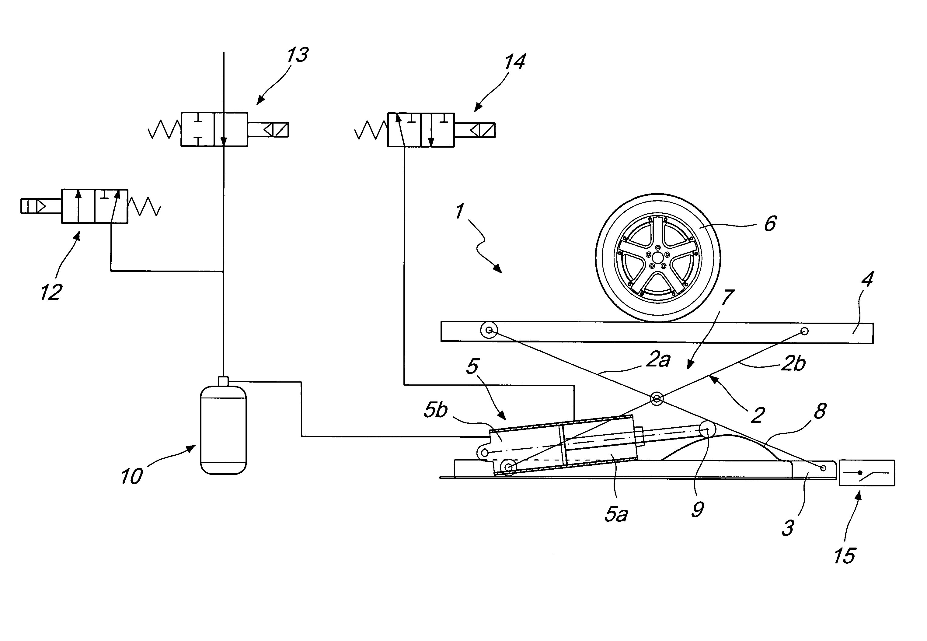
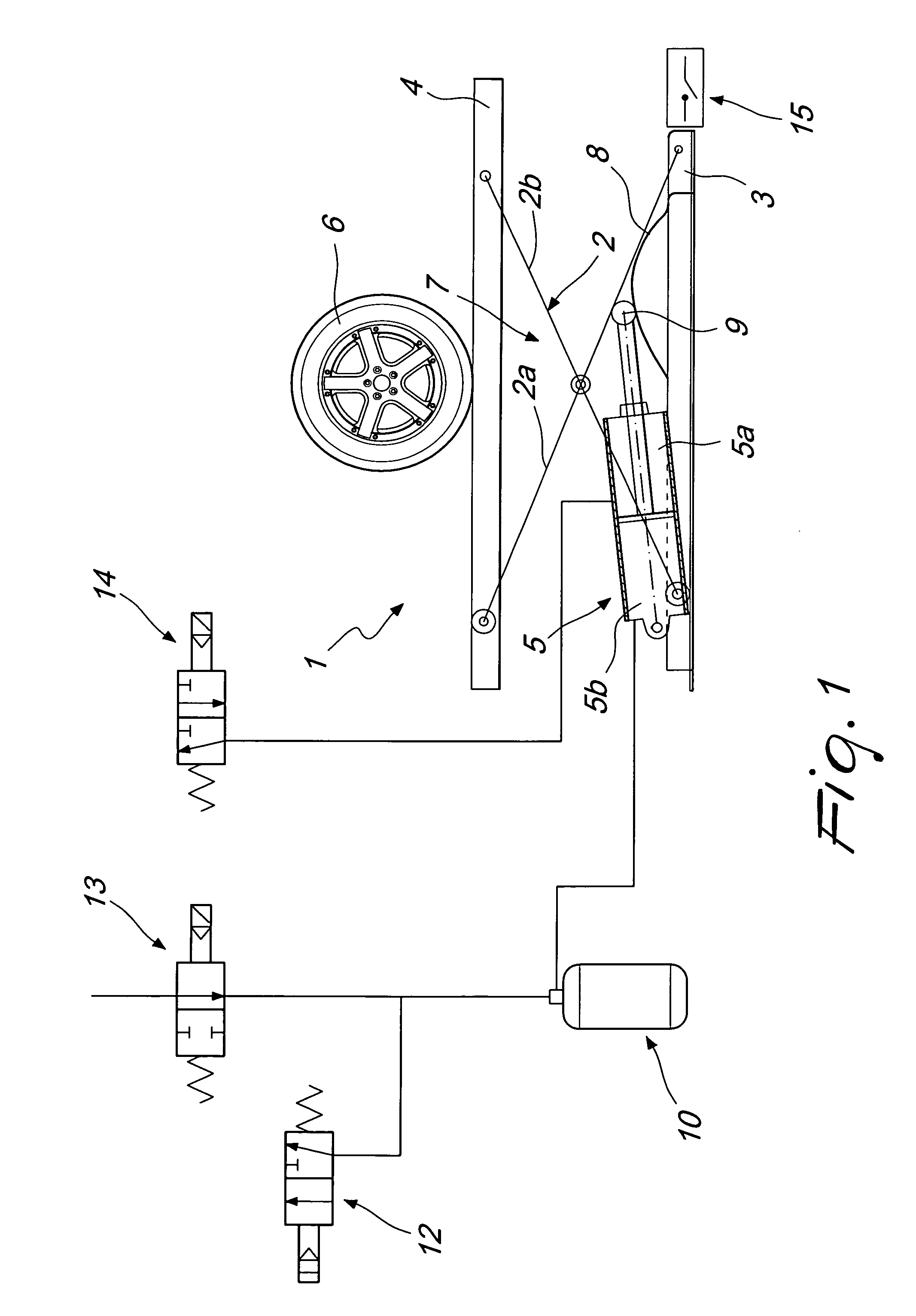
[0019]With reference to the figures, a lifting device, particularly for lifting wheels of vehicles and the like, for wheel balancing and tire removing machines, generally designated by the reference numeral 1, comprises a scissor-like frame 2, which is interposed between at least two flat and mutually parallel elements 3 and 4 for their mutual translational motion as a consequence of the action of motor means 5 that are functionally associated with the scissor-like frame 2.

[0020]More precisely, the two elements 3 and 4 are arranged in a horizontal position and respectively define the lower base of the lifting device 1 and the resting surface thereof on which a wheel 6 or any other object to be lifted is to be rested.

[0021]As regards the scissor-like frame 2, it is constituted by two rods 2a and 2b, which are hinged to each other so as to form an X-like shape and are hinged at one of their ends respectively to the lower base 3 or to the resting surface 4.

[0022]The remaining end of th...


PUM


Abstract

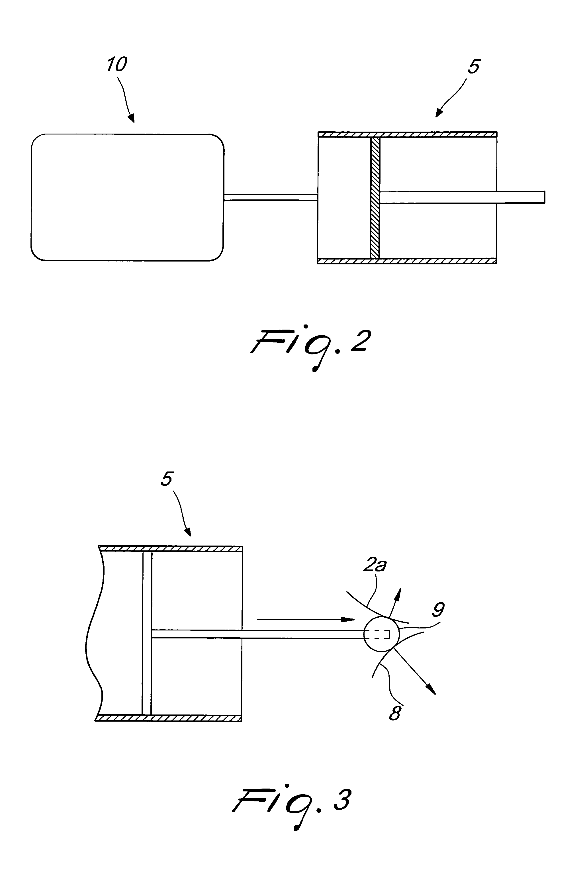
A lifting device, particularly for lifting wheels of vehicles and the like, for wheel balancing and tire removing machines, comprising a scissor-like frame, which is interposed between at least two flat and mutually parallel elements for their mutual translational motion as a consequence of the action of motor means functionally associated with the scissor-like frame, the lifting device further comprising a cam-type profiled element, which can be engaged functionally with the motor for dynamic and static balancing between the thrust force generated by the motor and the contrast force of the scissor-like frame in addition to the weight of the object to be lifted, which is arranged on one of the two flat and parallel elements, in all the operating positions of the lifting device.

Description

[0001]This is a continuation-in-part of U.S. patent application Ser. No. 12 / 453,797, filed on May 22, 2009.[0002]The present invention relates to a lifting device, particularly for lifting wheels of vehicles and the like, for wheel balancing and tire removing machines.BACKGROUND OF THE INVENTION[0003]It is common practice, in the field of vehicle repair shops, to use wheel balancing machines on which it is necessary to mount the wheel to be balanced by inserting a shaft, arranged at a distance from the ground that ranges on average from 700 mm to 800 mm, in the hole of such wheel.[0004]Moreover, during the mounting of the wheel on the balancing machine, the wheel is centered on the above cited shaft by means of a conical device that acts on the central hole.[0005]This known method for mounting the wheel on a balancing machine suffers a number of drawbacks. Among these, one must include the fact that the wheel, which can weigh up to 70 kg, is generally lifted manually by the operator...

Claims


Application Information

Patent Timeline
Patent Type & Authority Applications(United States)
IPC IPC(8): B66F7/06B66F7/08
CPCB66F7/065B66F7/085G06K7/10861
Inventor BUZZI, CARLO
Owner BUZZI CARLO
Learn More