
Fluid power control system for mobile load handling equipment

a technology of mobile load handling equipment and fluid power control system, which is applied in the direction of mechanical equipment, operating means/releasing devices of valves, servomotors, etc., can solve the problems of preventing highly accurate control of actuators, allowing accumulation of errors, and co-operating load-engaging members to become uncoordinated

Active Publication Date: 2013-10-24
CASCADE CORP
View PDF3 Cites 15 Cited by
  • Summary
  • Abstract
  • Description
  • Claims
  • Application Information

AI Technical Summary

Benefits of technology

This patent relates to improving fluid power control systems for hydraulically actuated multiple load-engaging members, such as forklifts or industrial vehicles. The problem is that these systems often have unintended differences in the movements of their load-engaging members, which can cause them to become uncoordinated. Previous attempts to solve this problem have either failed to provide accurate control or have limited the speed at which the actuators can complete their movements. The invention proposes a new system that uses sensors to detect and measure the movements of the load-engaging members, allowing for more precise control and synchronization. This system can be used in various hydraulic control systems and can improve the speed and efficiency of the load-engaging members.

Problems solved by technology

Although such differences are sometimes intended, they usually are unintended and cause the cooperating load-engaging members to become uncoordinated.
However, such flow divider / combiner valves are capable of controlling only roughly approximate movements of separate hydraulic actuators, with the result that their presence in any hydraulic control system prevents highly accurate control of the actuators and allows accumulated errors.
Other prior systems, which attempt to automatically correct unintended differences in the respective simultaneous movements of separate hydraulic actuators by monitoring their respective positions to provide feedback to respective hydraulic control valves, either variably regulate the separate control valves simultaneously, or completely block one of the valves until the correction has been completed, thereby substantially limiting the speed with which the actuators are able to complete their intended movements.

Method used


Image

  • Fluid power control system for mobile load handling equipment
  • Fluid power control system for mobile load handling equipment
  • Fluid power control system for mobile load handling equipment

Examples


Embodiment Construction

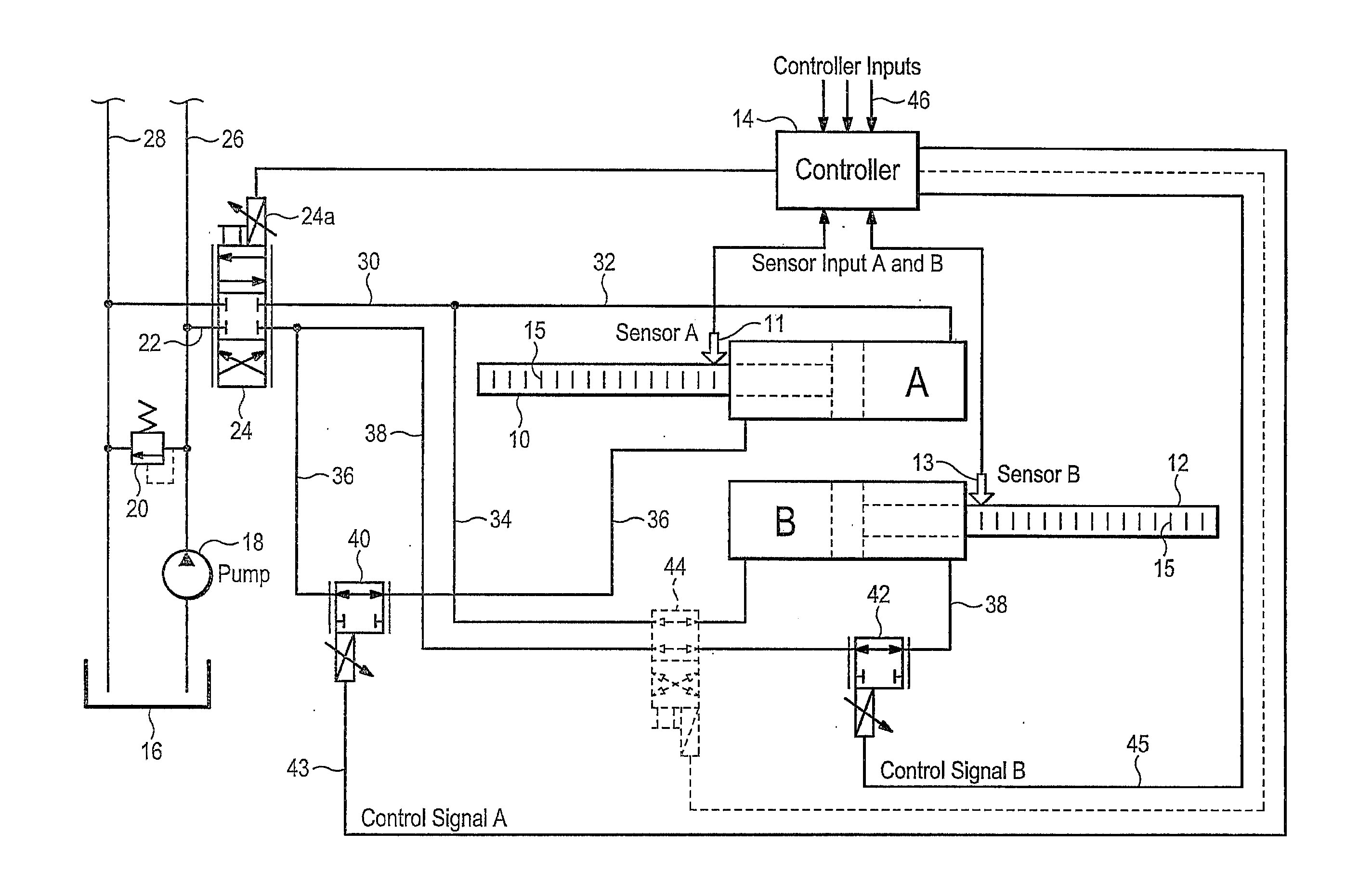
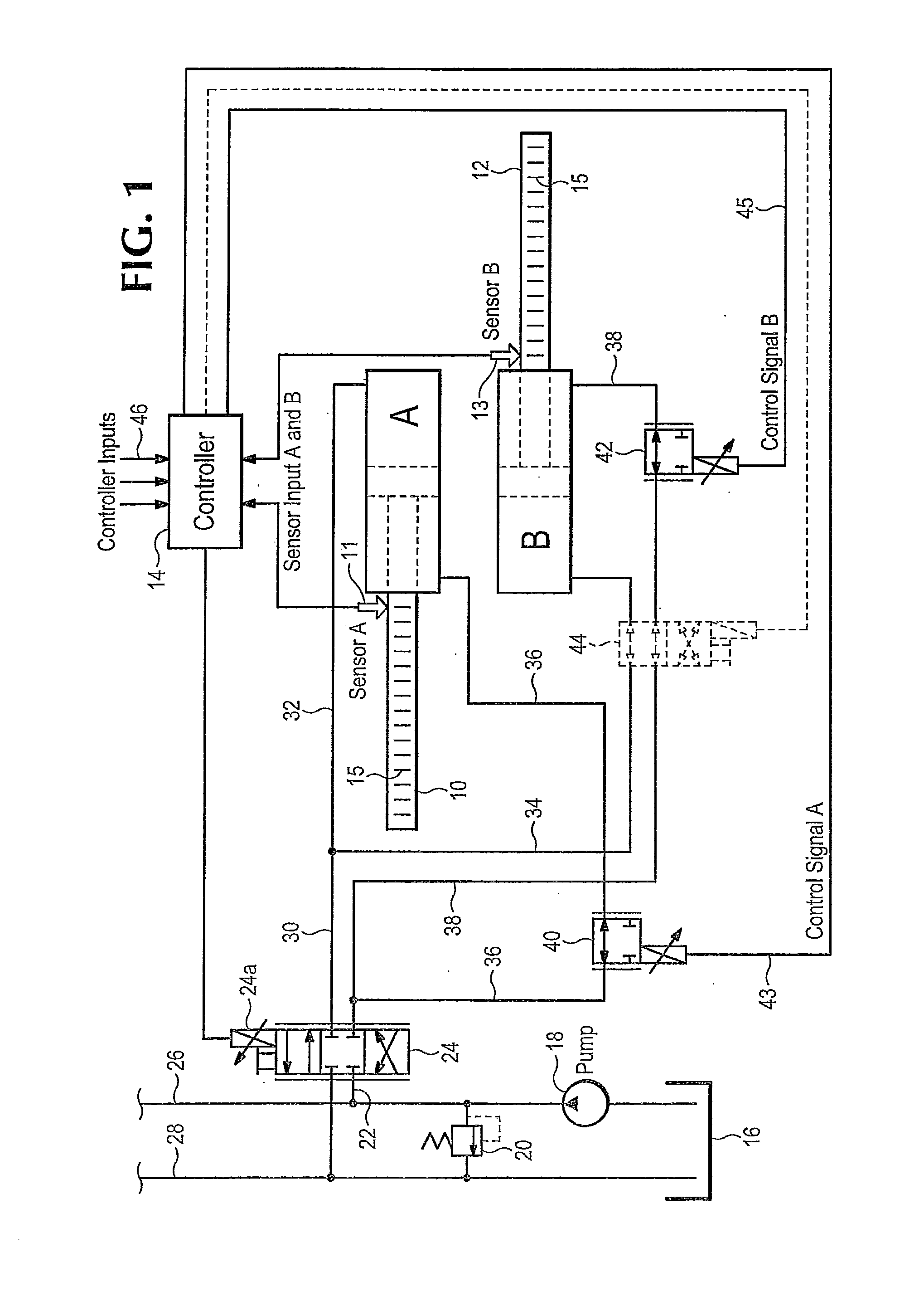
[0006]FIG. 1 shows a pair of exemplary linear hydraulic actuators in the form of separate, laterally-extending, oppositely-facing hydraulic piston and cylinder assemblies A and B. In general, oppositely-facing piston and cylinder assemblies are extremely common arrangements on lift truck load-handling carriages. Alternatively, the hydraulic actuators A and B could be of a rotary hydraulic motor type, depending upon the load-handling application.

[0007]An exemplary type of piston and cylinder assembly suitable for actuators A and B in the present disclosure is a Parker-Hannifin piston and cylinder assembly as shown in U.S. Pat. No. 6,834,574, the disclosure of which is hereby incorporated by reference in its entirety. Such piston and cylinder assembly includes an optical sensor, such as sensor 11 or sensor 13 in FIG. 1, capable of reading finely graduated unique incremental position indicia, indicated schematically as 15, along the lengths of each respective piston rod 10 or 12. As ex...


PUM


Abstract

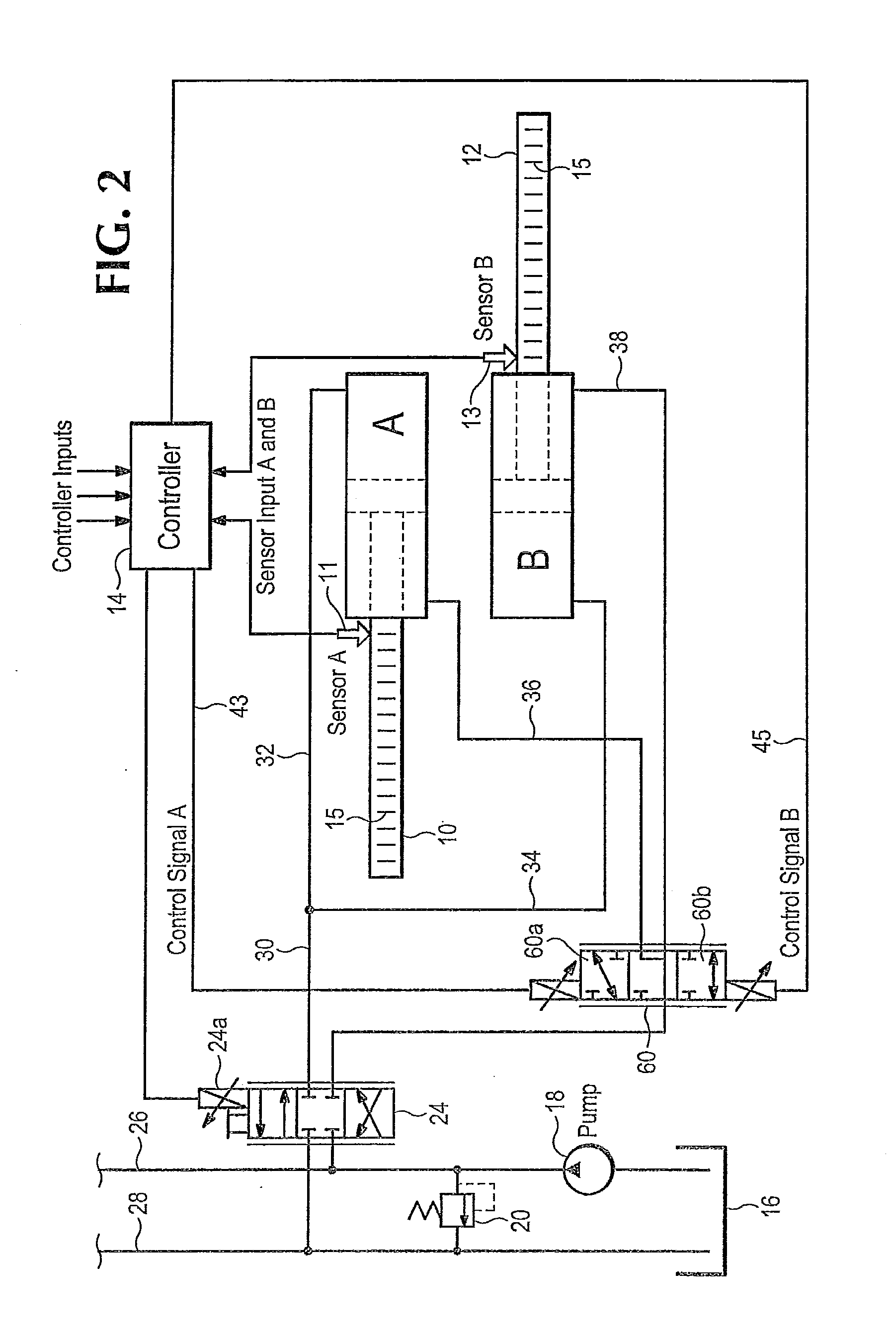
A fluid power control system for load handling mobile equipment includes a pair of hydraulic actuators for moving respective cooperating load-engaging members selectively toward or away from each other, or in a common direction, at respective asynchronous speeds to selectively attain either synchronous or asynchronous respective positions of the actuators. The actuators have sensors enabling a controller to monitor their respective movements and correct unintended differences in the actuators' respective movements, such as unintended differences in relative intended positions, speeds, or rates of change of speeds. Respective hydraulic valves responsive to the controller separately and nonsimultaneously decrease respective flows through the respective actuators to more accurately and rapidly correct differences from the intended relative movements of the actuators.

Description

BACKGROUND OF THE INVENTION[0001]This invention relates to improvements in fluid power control systems for hydraulically actuated, cooperating multiple load-engaging members normally mounted on lift trucks or other industrial vehicles. The multiple load-engaging members may be load-handling forks, clamp arms for load surfaces of curved, planar or other configurations, split clamp arms for handling multiple loads of different sizes simultaneously, layer picker clamp arms and their supporting booms, upenders, or other multiple load-engaging members movable cooperatively, but often differently, by linear or rotary hydraulic actuators. Differences in the respective cooperative movements of the respective multiple load-engaging members may include one or more differences in position, speed, acceleration, deceleration, and / or other variables. Although such differences are sometimes intended, they usually are unintended and cause the cooperating load-engaging members to become uncoordinate...

Claims


Application Information

Patent Timeline
IPC IPC(8): F16K31/02
CPCB66F9/22F15B11/22F15B15/2846F15B2211/30585F15B2211/3059F15B2211/315F15B2211/327F15B2211/40515F15B2211/413F15B2211/41527F15B2211/41536F15B2211/426F15B2211/427F15B2211/50518F15B2211/5153F15B2211/526F15B2211/527F15B2211/6336F15B2211/6654F15B2211/6656F15B2211/7053F15B2211/7128F15B2211/75F15B2211/755F15B2211/782
Inventor MCKERNAN, PAT S.NAGLE, GREGORY A.
Owner CASCADE CORP
Learn More