
Differential MRAM structure with relatively reversed magnetic tunnel junction elements enabling writing using same polarity current

a technology of magnetic tunnel junction elements and differential mram, which is applied in the direction of information storage, static storage, digital storage, etc., can solve the problems of inability to write using the same polarity current, memory circuit may be considered defective, and inherent risk of read-disturb errors, so as to simplify the manufacturing process

Active Publication Date: 2013-10-17
TAIWAN SEMICON MFG CO LTD
View PDF4 Cites 42 Cited by
  • Summary
  • Abstract
  • Description
  • Claims
  • Application Information

AI Technical Summary

Benefits of technology

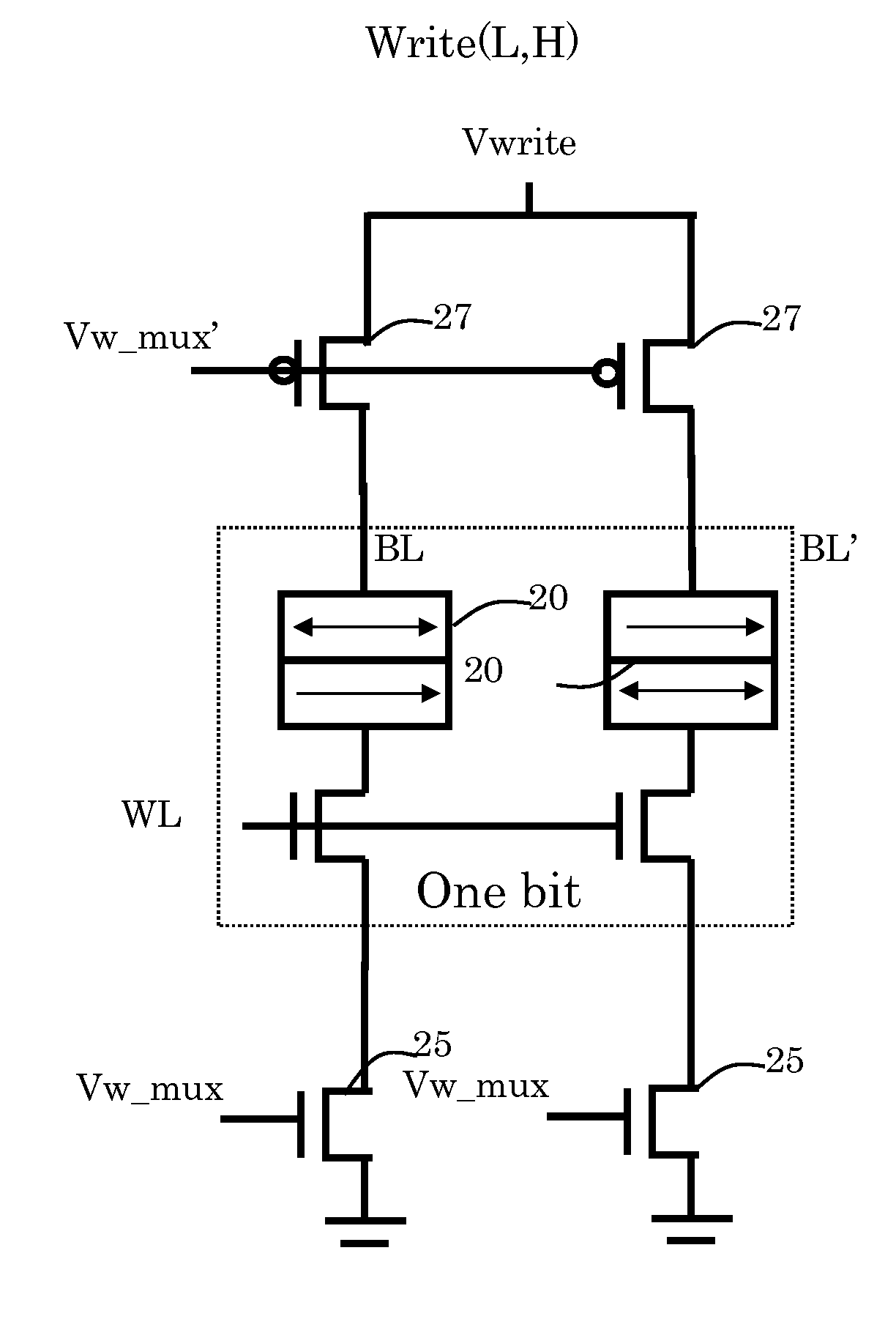
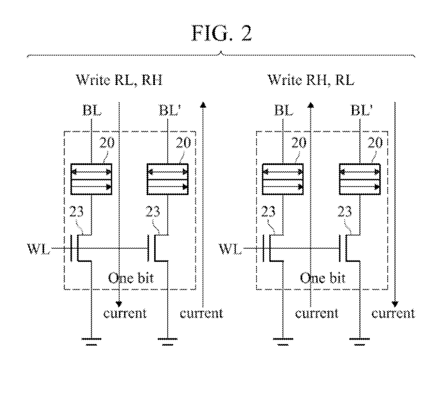
The patent is about a memory device that uses two complementary MTJ elements to store data. These elements can be arranged in both regular and reverse order, which simplifies the manufacturing process. This invention allows for the MTJ elements to have different layers ordered in different parts of the circuit, making them easier to manufacture and use.

Problems solved by technology

Therefore, there is a potential that some combinations of a present resistance state and a particular read current polarity may inadvertently change the state of the MTJ element during a read operation.
This is known as a read disturb error.
Inasmuch as the high and low resistance values of the numerous MTJ elements are distributed over a range, a problem is encountered in defining the best threshold value to use when attempting to discern whether the MTJ element is in its high or low resistance state.
According to product selection criteria, at some number of defective bits (possibly only one bit), the memory circuit may be considered defective.
There seems to be an inherent risk of read-disturb errors and a need to limit the amplitude of read current bias for all bit cells to an amplitude that will not disturb the resistance state of the most sensitive MTJ element in the memory array.

Method used


Image

  • Differential MRAM structure with relatively reversed  magnetic tunnel junction elements enabling writing using same polarity current
  • Differential MRAM structure with relatively reversed  magnetic tunnel junction elements enabling writing using same polarity current
  • Differential MRAM structure with relatively reversed  magnetic tunnel junction elements enabling writing using same polarity current

Examples


Embodiment Construction

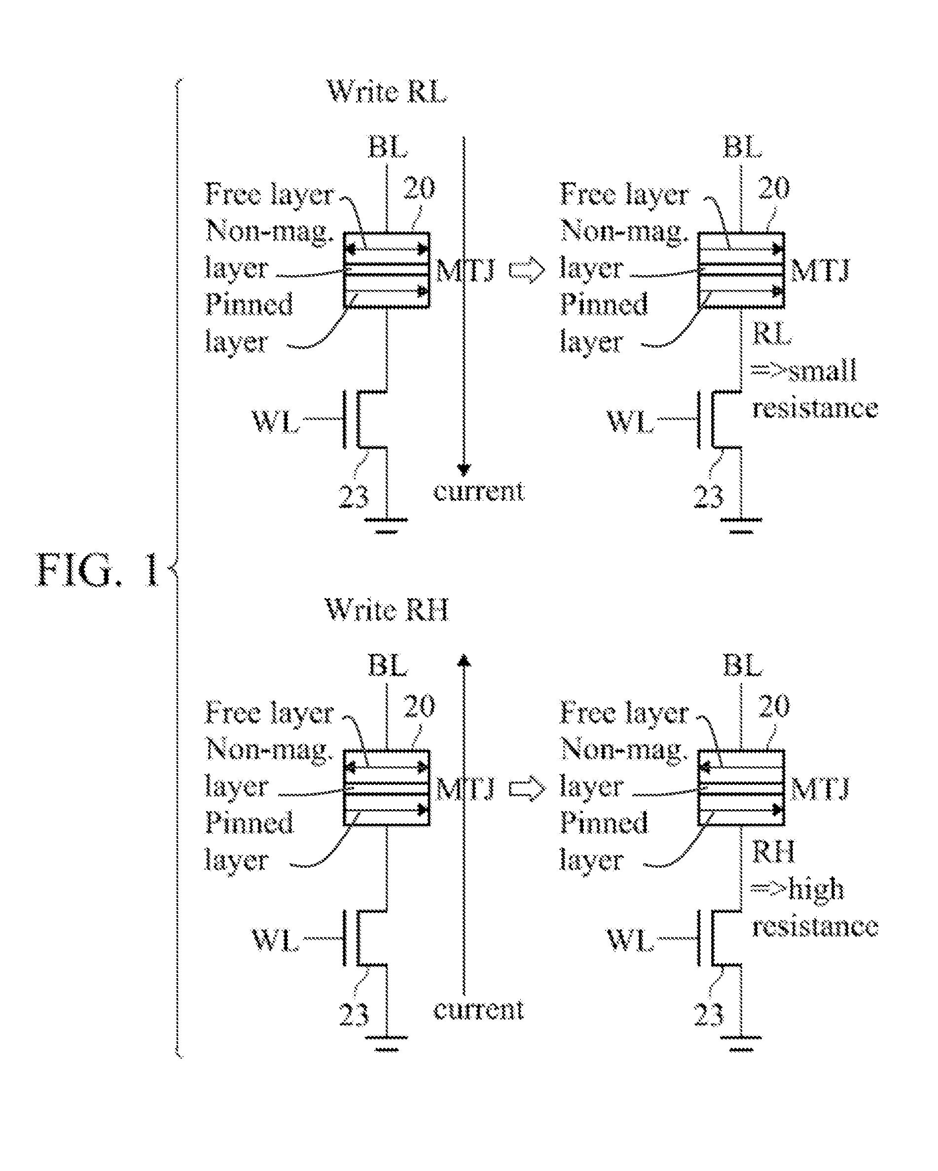
[0022]One magnetic layer of a magnetoresistive magnetic tunnel junction (MTJ) element has a permanently aligned field and is generally termed the pinned layer or reference layer. The other magnetic layer has a changeably-aligned field that either is aligned with the field of the pinned layer (parallel and with the same north / south polarity), or directly opposite (anti-parallel) to the field of the pinned layer. The layer with the changeable field orientation is termed the free layer or sense layer. The free and pinned layers are separated by a barrier layer.

[0023]When the fields in the two layers are parallel, the electrical resistance to current flowing through the two layers and the separating conductive barrier layer of the magnetic terminal junction (MTJ) element is relatively lower and when the fields in the two layers are anti-parallel, the electrical resistance is relatively higher. According to Ohm's Law (V=IR), the resistance of the element produces a voltage when a current...


PUM


Abstract

A magnetoresistive memory has first and second magnetic tunnel junction (MTJ) elements operated differentially, each with a pinned magnetic layer and a free magnetic layer that can have field alignments that are parallel or anti-parallel, producing differential high and low resistance states representing a bit cell value. Writing a high resistance state to an element requires an opposite write current polarity through the pinned and free layers, and differential operation requires that the two MTJ elements be written to different resistance states. One aspect is to arrange or connect the layers in normal and reverse order relative to a current bias source, thereby achieving opposite write current polarities relative to the layers using the same current polarity relative to the current bias source. The differentially operated MTJ elements can supplement or replace single MTJ elements in a nonvolatile memory bit cell array.

Description

BACKGROUND[0001]Spin-transfer torque magnetoresistive random access memories (STT-MRAM) are nonvolatile memories that store changeable bit data values in the relative orientations of magnetic fields in one or more magnetic terminal junction (MTJ) elements that comprise a fixed magnetic layer and a changeable magnetic layer, separated by a nonmagnetic conductive barrier.[0002]A binary data value is represented in an MTJ element, by orienting the changeable magnetic layer parallel to the fixed magnetic layer, which is a low resistance state, or anti-parallel, which is a high resistance state. For reading out the stored bit data value, the serial resistance through the layers is detected by comparison with a threshold value, typically comparing a current or voltage parameter that varies with resistance, versus a threshold of current or voltage representing a resistance between the high and low resistance states.[0003]When writing a data value to an MTJ element, a write bias current of ...

Claims


Application Information

Patent Timeline
IPC IPC(8): G11C11/16
CPCG11C11/1659G11C11/1673G11C11/1675G11C29/74G11C11/15
Inventor LIN, KAI-CHUNYU, HUNG-CHANGCHIH, YUE-DERLIN, CHUN-JUNG
Owner TAIWAN SEMICON MFG CO LTD
Learn More