
Ultrasonic welding device and method of operating said device

a welding device and ultrasonic technology, applied in the direction of non-electric welding apparatus, manufacturing tools, other domestic objects, etc., can solve the problems of insufficient force to damage the areas of workpieces, degree of uncertainty with respect to the normal integrity of prior welding, mechanical attachment or stress concentration, etc., to achieve the effect of complex geometry, lack of reproducibility, and time-consuming

Active Publication Date: 2013-10-10
AIRBUS HELICOPTERS DEUT GMBH
View PDF3 Cites 9 Cited by
  • Summary
  • Abstract
  • Description
  • Claims
  • Application Information

AI Technical Summary

Benefits of technology

The invention is an ultrasonic welding device that adds additional functions to a traditional ultrasonic robot head, allowing for pick-up or passive clamping of workpieces from one side. This device provides the advantage of free movements relative to fixed workpieces, avoiding the limitations of existing ultrasonic welding devices. This makes it easier to assemble binder preform elements or mount small preform patches onto big fixed preforms for local reinforcement of load critical areas in carbon fiber reinforced plastics (CFRP) components, such as applied for aircraft doors. The device also eliminates the need for costly and time-consuming manual labor and complex metal patterns for every welding operation. The invention's pick member includes a press pad for stability and orientation. Overall, this invention saves time, reduces costs, improves assembly process automation, and increases part quality, leading to the substitution of more complex machinery.

Problems solved by technology

Additionally, control must be established over the mechanical waves and forces that are emitted from the working area so that these forces are not strong enough to damage those areas of the workpieces remote from the work spot.
Absence of positive control over these forces has resulted in a degree of uncertainty with respect to the normal integrity of prior welds, bonds, mechanical attachments or stress concentrations.

Method used


Image

  • Ultrasonic welding device and method of operating said device
  • Ultrasonic welding device and method of operating said device
  • Ultrasonic welding device and method of operating said device

Examples


Embodiment Construction

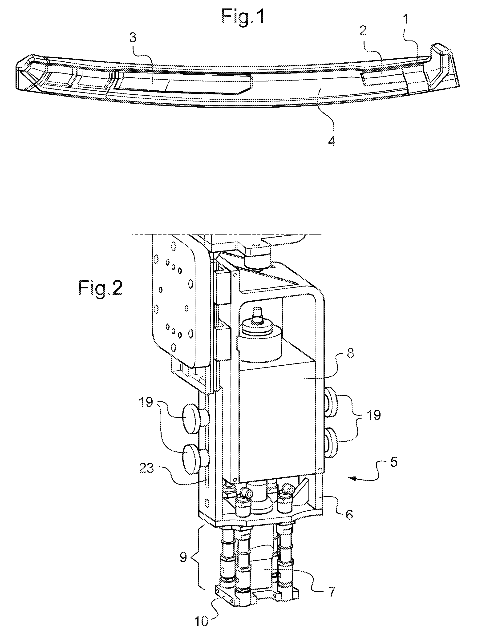
[0036]According to FIG. 1 workpieces, such as small patches of preforms 1, 2, 3 are attached to a fixed preform 4 on a tooling as further workpiece made of carbon fibre reinforced plastics (CFRP) components. Said preforms 1-4 are defined as composite elements of partly or fully impregnated fabric material.

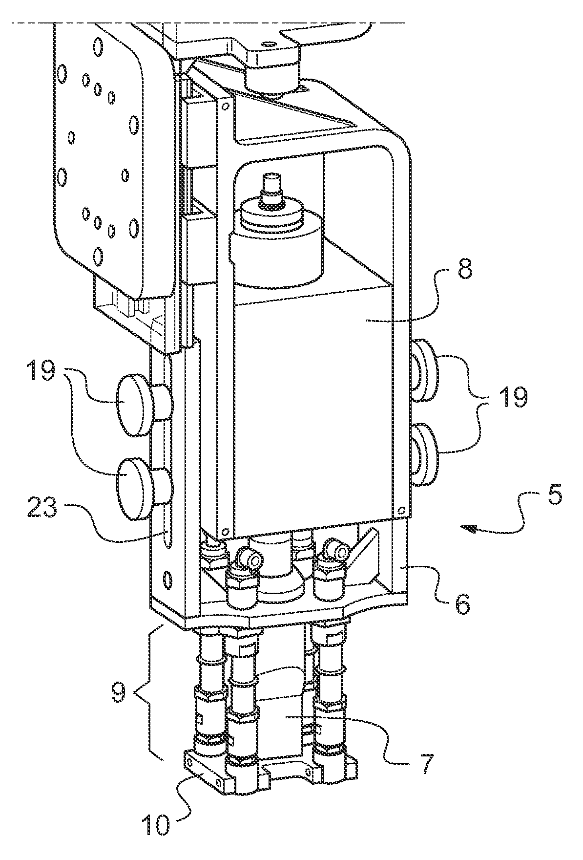
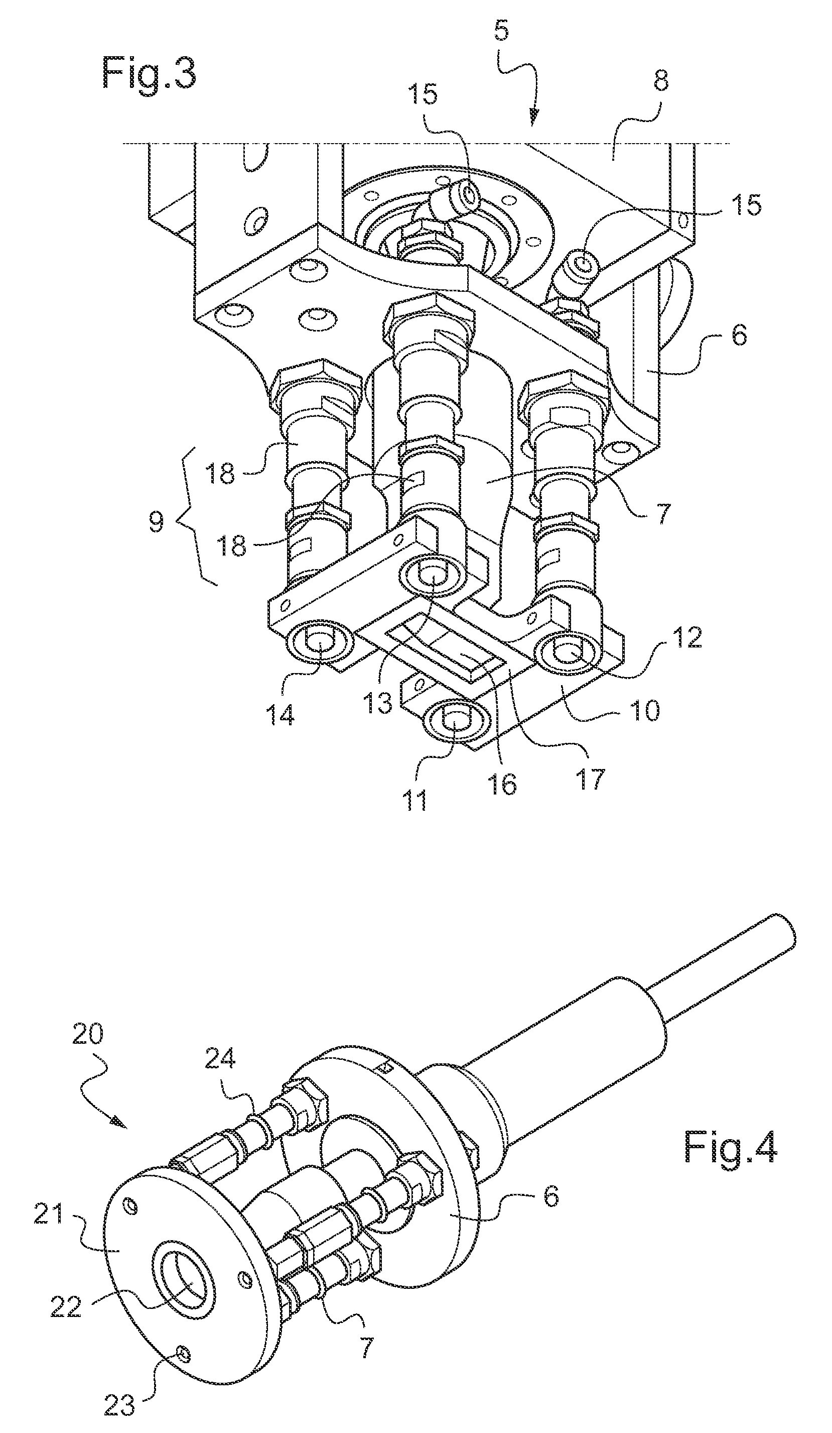
[0037]According to FIGS. 2 and 3 an ultrasonic welding device 5 is mounted inside an adapter frame 6. Control means (not shown) are provided for control of said ultrasonic welding device 5. An ultrasonic horn 7 is actuated by activation means 15 comprising a converter 8 of the ultrasonic welding device 5. The ultrasonic horn 7 is oriented parallel to said adapter frame 6. The adapter frame 6 is mounted to two opposed surfaces of the converter 8 with adjustment means 19 allowing adjustment of the adapter frame 6 parallel to said ultrasonic horn 7.

[0038]A pick member 9 is mounted to said adapter frame 6 with the ultrasonic horn 7 centrally inside. The pick member 9 comprises a press ...


PUM

PropertyMeasurementUnit
pressureaaaaaaaaaa
pressureaaaaaaaaaa
distanceaaaaaaaaaa

Abstract

The invention is related to an ultrasonic welding device (5) comprising: an adapter frame (6); an ultrasonic horn (7) driven by a adapter frame mounted converter (8). A pick member (9) comprises grippers (11-14). Passive clamping means are provided with a press pad (10). Control means and activation means (15) are provided for controlled activation of the pick member (9) and the ultrasonic horn (7). The invention is further related to a method of operating said device.

Description

CROSS REFERENCE TO RELATED APPLICATIONS[0001]This application claims priority to European patent application No. EP 12400009.2 filed Apr. 5, 2012, the disclosure of which is incorporated in its entirety by reference herein.BACKGROUND OF THE INVENTION[0002](1) Field of the Invention[0003]The invention is related to an ultrasonic welding device with the features of the preamble of claim 1. The invention is further related to a method of operating said device with the features of the preamble of claim 13.[0004](2) Description of Related Art[0005]Ultrasonic welding technology is used to weld elements to increase energy / time efficiency.[0006]The document CN101391343 A discloses an ultrasonic welding machine clamper fast conversion device, comprising a welding machine seat, a clamper, and additionally a welding head directional plate, a welding pad plate, a Y axis trimming plate and an X axis trimming plate with grooves of a locating pin of a locating plate, a trimming button and a bottom...

Claims


Application Information

Patent Timeline
Patent Type & Authority Applications(United States)
IPC IPC(8): B29C65/08
CPCB23K20/10Y10T156/17B29C65/08B29L2031/3076B29L2031/724B29C65/7847B29C66/532B29C66/721B29C66/7212B29C66/8161B29C66/8167B29C66/863B23K20/106B29K2307/04B29C66/1122B29C66/61
Inventor WEILAND, FRANKBEIER, UWEGUBERNATIS, STEFANWEIMER, CHRISTIAN
Owner AIRBUS HELICOPTERS DEUT GMBH
Learn More