Systems, methods, and non-transitory, computer-readable media for performing image processing using controllers that perform distinct functions

Active Publication Date: 2013-10-03
BROTHER KOGYO KK
View PDF1 Cites 7 Cited by
  • Summary
  • Abstract
  • Description
  • Claims
  • Application Information

AI Technical Summary

Benefits of technology

The patent describes a new type of image recording device that can reduce costs by reducing the work of the controller that processes the image. This allows for a more efficient and cost-effective image recording process.

Problems solved by technology

A controlling device (i.e., a first control section) for performing image processing requires relatively expensive components, such as a central processing device and an arithmetic circuit.
As loads applied to the controlling device by processing that is not the image processing increases, resources of the controlling device are not available for image processing.
To realize the required image processing, more expensive components are required in the controlling device, which leads to increases in costs associated with the image recording apparatuses.

Method used


Image

  • Systems, methods, and non-transitory, computer-readable media for performing image processing using controllers that perform distinct functions
  • Systems, methods, and non-transitory, computer-readable media for performing image processing using controllers that perform distinct functions
  • Systems, methods, and non-transitory, computer-readable media for performing image processing using controllers that perform distinct functions

Examples


Embodiment Construction

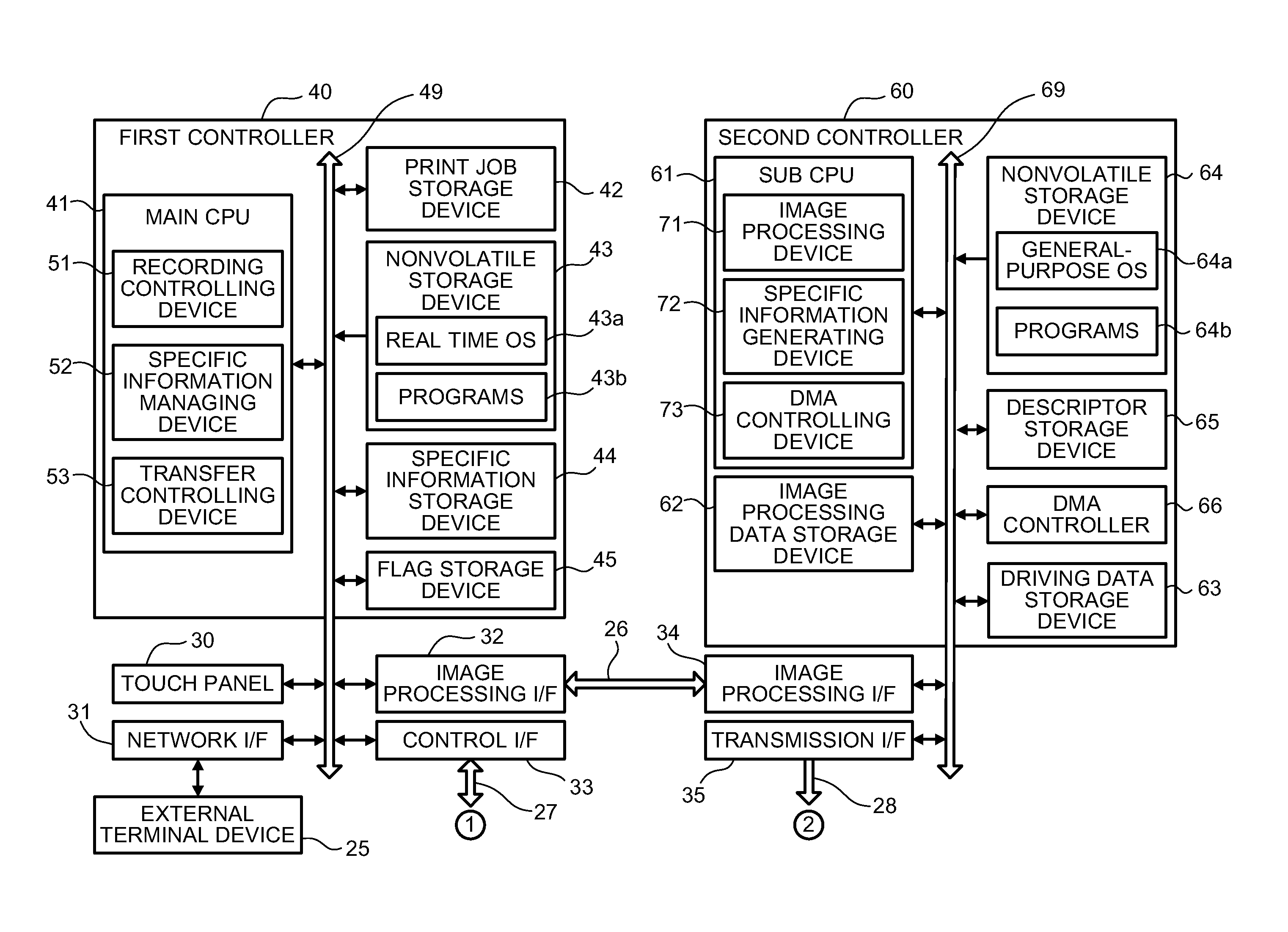
[0026]Embodiments now are described in detail with reference to the accompanying drawings, wherein similar reference numerals may correspond to similar components throughout the various drawings.

[0027]An image recording apparatus according to the present invention may comprise an inkjet printer 101.

[0028]As shown in FIG. 1, the inkjet printer 101 may comprise a transferring mechanism 20 configured to transfer a recording medium (e.g., a sheet P), an inkjet print head 1 configured to eject ink (e.g., black ink, ink of other colors) onto the sheet P transferred by the transferring mechanism 20, and a controlling device 100 configured to control the inkjet printer 101.

[0029]The transferring mechanism 20 may be configured to transfer the sheet P in a feeding direction (e.g., from the left to right in FIG. 1). The transferring mechanism 20 may comprise a first transferring section 6, a second transferring section 7, a platen 10, a separation plate 13, and an output tray 14.

[0030]The firs...


PUM


Abstract

An image recording apparatus includes a first controller, a second controller, and a recording device. The first controller receives image data. The first controller transmits the image data to the second controller in response to receiving the image data. The second controller generates driving data based on the image data in response to receiving the image data. The recording device transmits a driving data transmission request to the first controller. The first controller transmits a driving data transmission instruction to the second controller in response to receiving the driving data transmission request from the recording device. The second controller transmits the driving data to the recording device in response to receiving the driving data transmission instruction from the first controller. The recording device records the image on the recording medium based on the driving data in response to receiving the driving data from the second controller.

Description

CROSS REFERENCE TO RELATED APPLICATION[0001]This application claims priority to Japanese Patent Application No 2012-082731 filed on Mar. 30, 2012, the disclosure of which is incorporated herein by reference.BACKGROUND OF THE INVENTION[0002]1. Field of the Invention[0003]The present invention relates generally to image processing and more specifically to systems, methods, and non-transitory, computer-readable media for performing image processing using controllers that perform distinct functions.[0004]2. Description of Related Art[0005]A known image recording apparatus performs parallel processing to increase an image recording speed.[0006]A known printing device includes a printing mechanism, a first control section, and a second control section. The first control section performs image processing that converts print data transmitted from an external device into intermediate codes. The second control section performs image processing that converts the intermediate codes received fro...

Claims


Application Information

Patent Timeline
IPC IPC(8): G06K15/02
CPCG03G15/5025G06F9/3877
Inventor TSUCHIYA, TAISUKE
Owner BROTHER KOGYO KK
Why Eureka
Try Eureka