
Gpu-based rip architecture

a rip architecture and gpu technology, applied in the field of raster image processing, can solve the problems of reducing transfer time, gpus may not be used to their full potential, and requiring more bandwidth than a peripheral bus can provide,

Active Publication Date: 2013-10-03
CANON KK
View PDF10 Cites 11 Cited by
  • Summary
  • Abstract
  • Description
  • Claims
  • Application Information

AI Technical Summary

Benefits of technology

The present invention provides a method and system for printing document data in page description language format using a plurality of graphics processing units via a video interface. The method involves converting the document data to a set of rendering commands, assigning each tile in the document to a graphics processing unit, rendering the tiles in parallel, transmitting the rendered tiles to a print head controller, and outputting the tiles to form a complete band for printing. The technical effects of this invention include improved printing speed and quality.

Problems solved by technology

Transferring the pixel data from GPU to main memory and from main memory to another device may require more bandwidth than such a peripheral bus can provide.
In this case, the GPUs will not be used to their full potential due to the bottleneck of output bandwidth from the transfer to the CPU or a network interface.
Although the data transfer time may be reduced, the extra time required for compression, data transfer and decompression negates the benefit.

Method used


Image

  • Gpu-based rip architecture
  • Gpu-based rip architecture
  • Gpu-based rip architecture

Examples


Embodiment Construction

[0041]Where reference is made in any one or more of the accompanying drawings to steps and / or features, which have the same reference numerals, those steps and / or features have for the purposes of this description the same function(s) or operation(s), unless the contrary intention appears.

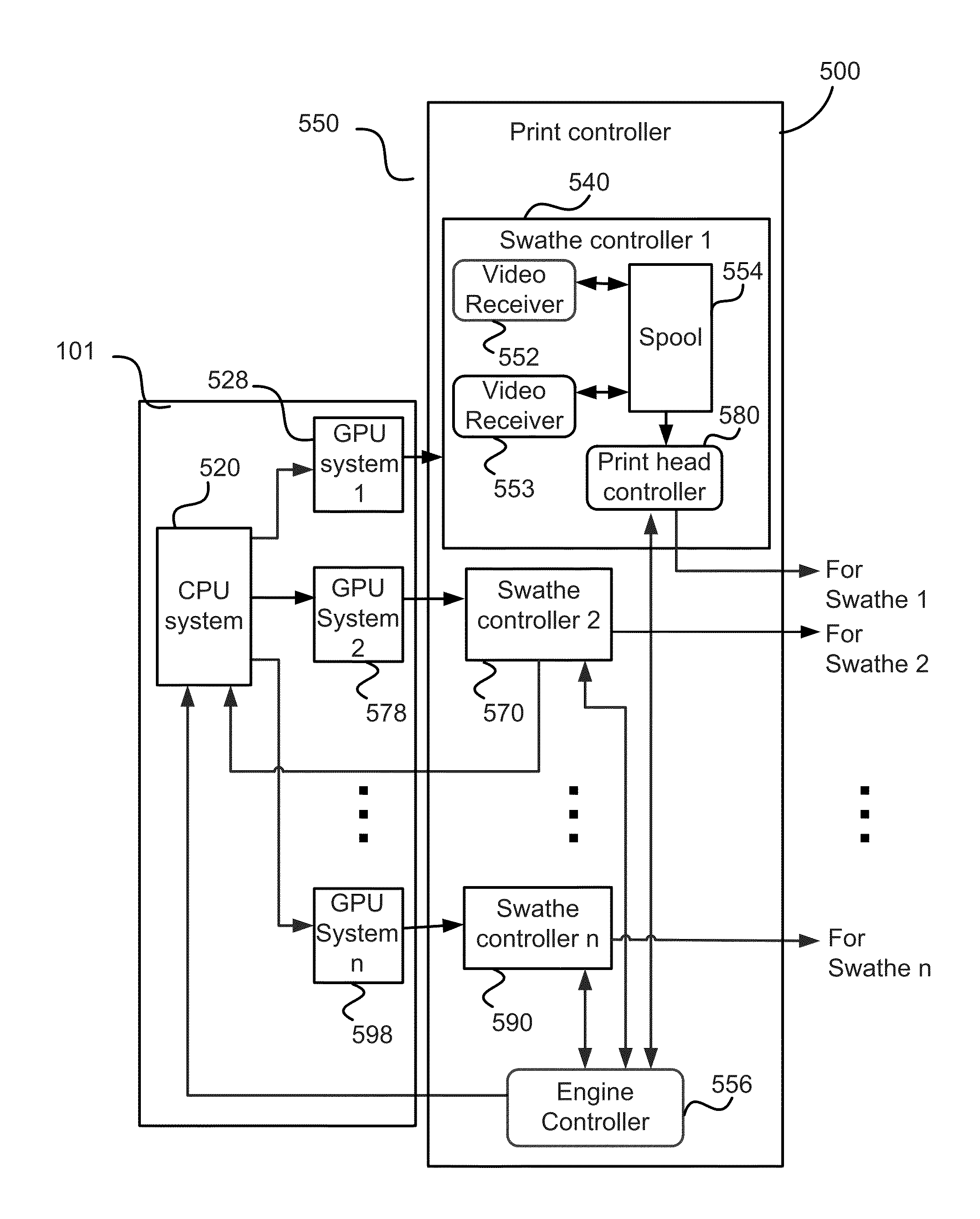
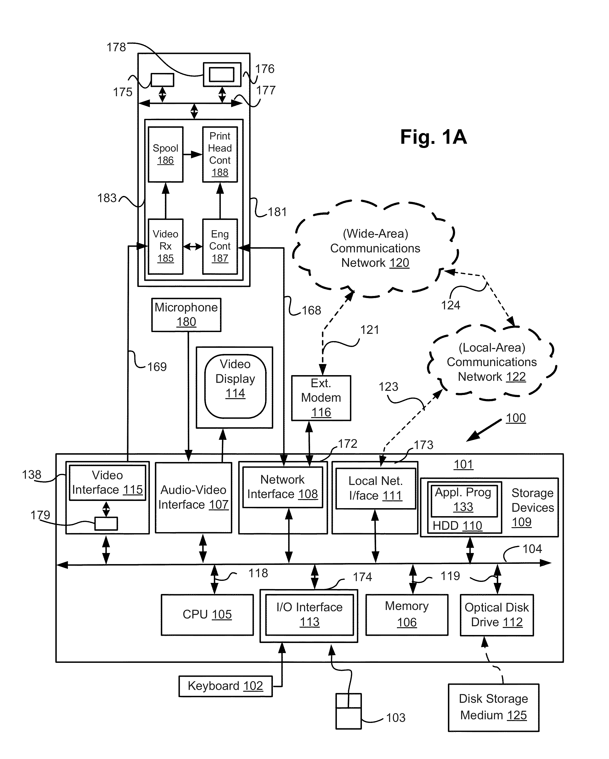
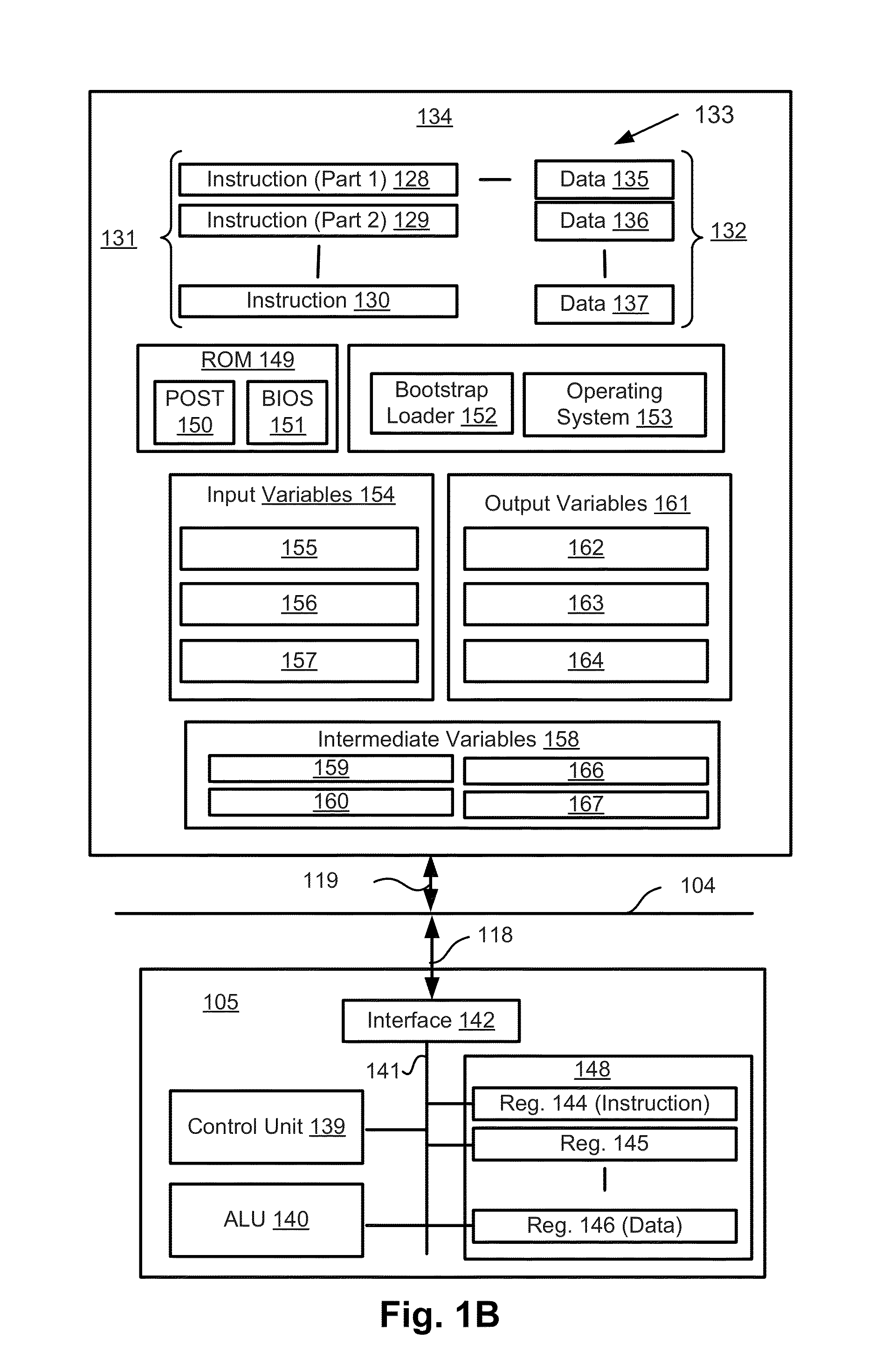
[0042]A GPU-based RIP computer system 100 is described below with reference to FIGS. 1A and 1B. The computer system 100 may be used for implementing printing methods as described below.

[0043]The system 100 comprises a Graphics Processing Unit (GPU) card 138 configured within a computer module 101. As seen in FIG. 1A, the GPU card 138 comprises a memory unit 179. The memory unit 179 is typically formed from semiconductor random access memory (RAM). The GPU card 138 also comprises a video interface 115.

[0044]The computer module 101 is connected to an associated print controller 183 configured within a printer 181. The computer module 101 is also connected, via a network card 172, to an engine control...


PUM


Abstract

A method of printing document data in page description language format using a plurality of graphics processing units. The plurality of tiles representing the document using the assigned graphics processing units are rendered in parallel with one another, and the rendered tiles are transmitted, bypassing the central processing units, from each of the graphics processing units to a corresponding one of a plurality of print head controllers, with the rendered tiles transmitted at a higher frequency than a frequency at which the plurality of tiles is output from each print head controller. The rendered tiles are repeatedly transmitted until each print head controller completes output of the previous band.

Description

REFERENCE TO RELATED PATENT APPLICATION(S)[0001]This application claims the benefit under 35 U.S.C. §119 of the filing date of Australian Patent Application No. 2012201865, filed 29 Mar. 2012, hereby incorporated by reference in its entirety as if fully set forth herein.TECHNICAL FIELD OF INVENTION[0002]The current invention relates to the field of raster image processing for high-speed digital printing presses.DESCRIPTION OF BACKGROUND ART[0003]Increasing speed of digital printers has created a need for matching high speed RIP (Raster Image Processing) systems. An RIP system converts Page Description Language (PDL) data, such as Portable Document Format (PDF) developed by Adobe Systems Inc., or XPS developed by Microsoft Corporation, into pixel data that can be used as input to a digital printer.[0004]Traditionally RIP systems have utilized general purpose processors (CPUs) or custom hardware. Recently, Graphics Processing Units (GPUs), originally designed for 3D rendering applicat...

Claims


Application Information

Patent Timeline
IPC IPC(8): G06K15/02
CPCG06K15/1813G06K15/1894G06K15/1857G06K15/10
Inventor QIAN, LENAWARREN, ZACHARY THEODOREDOWNING, ANDREW PETER
Owner CANON KK
Learn More