Integrated Laser Alignment Aid Using Multiple Laser Spots Out Of One Single Laser

a laser spot and laser technology, applied in the field of light curtains, can solve the problems of high fabrication cost, increased cost due to the addition of laser emitters for each transceiver bar, and incompatible modular transceiver bar configuration with laser alignment techniques, etc., to achieve easy fabrication and space-saving shape, enhance the accuracy of optical axis alignment, and facilitate the effect of fabrication

Active Publication Date: 2013-10-03
ROCKWELL AUTOMATION SWITZERLAND
View PDF12 Cites 0 Cited by
  • Summary
  • Abstract
  • Description
  • Claims
  • Application Information

AI Technical Summary

Benefits of technology

[0014]The radiation receiver may be just a target surface where the radiation pattern emitted by the opposing laser module is clearly visible and can be evaluated by an operator adjusting the position of the light curtain system. However, also more sophisticated sensor systems can be used for evaluating the position of the opposing stick. According to the present invention, the optical processing element is structured to form in a planar observation region, a plurality of light points arranged in an essentially straight line from the radiation of the laser radiation source. By splitting one laser spot into various spots an alignment accuracy can be reached which normally is only achieved by using more than one laser radiation sources.
[0030]According to the present invention, the optical processing element comprises a prismatic structure having a plurality of angled surfaces and a uniform base surface opposite to these angle surfaces. Such a structure may easily be produced and has the advantage of generating the desired radiation pattern in a very flexible and accurate way. In particular, by using different sizes of the particular prismatic areas, spots of differing brightness can be generated. The plurality of different prisms are all fabricated with one molding tool, if a molding technique is used. By partitioning the tool correspondingly, sharp edges can be achieved for the prismatic structure. Furthermore, by providing the base surface with an orientation regarding the optical axis of the incident alignment radiation beam so that it includes an angle different from 90° with the optical axis, the overall thickness of the optical processing element can be kept much more uniform, thus facilitating the molding process.

Problems solved by technology

This dedicated architecture of an emitter and receiver, however, has several drawbacks, for instance the fact that the fabrication costs are high, because each type of optical unit has to be fabricated differently.
However, this modular transceiver bar configuration is not compatible with laser alignment techniques that employ one laser module as a radiation emitter at each stick, but at different locations for the dedicated receiver and transmitter bar, respectively, as this is for instance shown in the published European patent EP 0889332 B1.
This concept, however, increases the costs due to the additional laser emitter for each transceiver bar.

Method used


Image

  • Integrated Laser Alignment Aid Using Multiple Laser Spots Out Of One Single Laser
  • Integrated Laser Alignment Aid Using Multiple Laser Spots Out Of One Single Laser
  • Integrated Laser Alignment Aid Using Multiple Laser Spots Out Of One Single Laser

Examples


Embodiment Construction

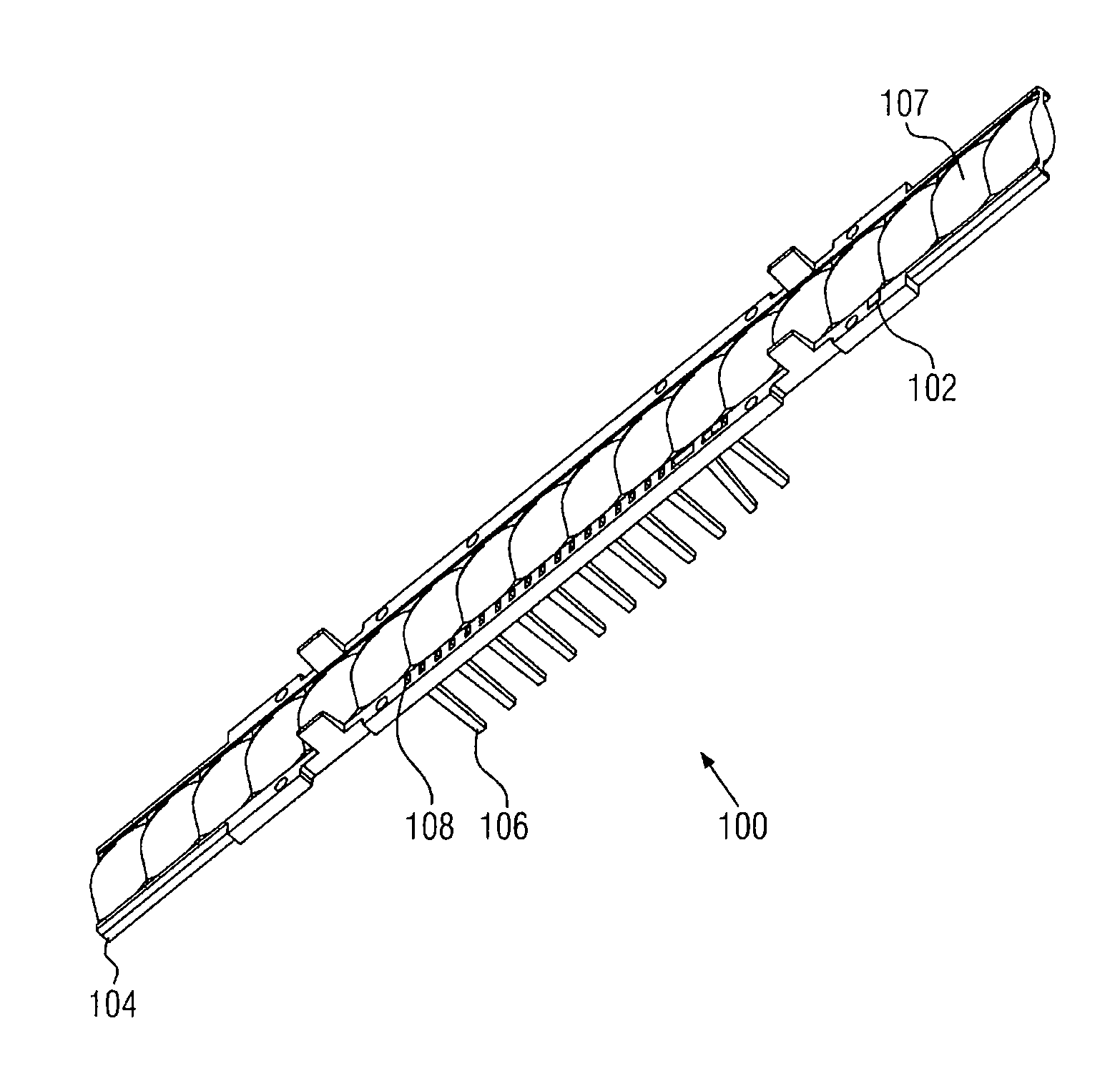
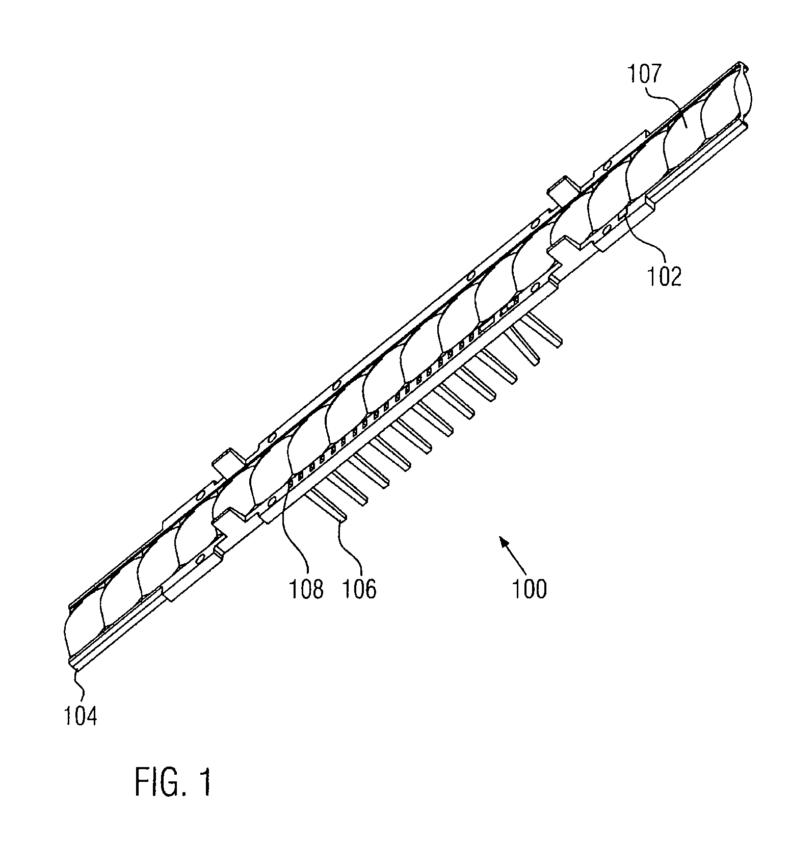
[0066]Referring now to FIG. 1, an optical unit according to the present invention is explained in more detail.

[0067]The optical unit 100 is designed to be mounted within a support element of a light curtain monitoring a protective field. The optical unit 100 is combining several optical functions as one integral part: Firstly, it accommodates an optical processing element 102 for generating a defined radiation pattern from the radiation which is emitted by an alignment radiation source (not shown in the figure). The optical processing element 102 may for instance comprise a micro-structured Diffractive Optical Element (DOE) which transforms the radiation emitted by a radiation source, such as a laser diode, into a pattern that can be used advantageously for aligning a support element to which the optical unit 100 is connected with respect to a second support element of a light curtain arranged in some distance thereto.

[0068]For a person skilled in the art, it is however clear that t...


PUM


Abstract

The present invention relates to light curtains, in particular safety light curtains, for monitoring a protective field. Furthermore, the present invention relates to optical units which are part of such a light curtain. An optical unit for an alignment system of a light curtain monitoring a protective field comprises an optical processing element for generating a defined radiation pattern from the radiation emitted by an alignment radiation source, and at least one additional optical functional element being formed integrally with the optical processing element.

Description

CROSS-REFERENCE TO RELATED APPLICATIONS[0001]This application is a continuation-in-part of U.S. application Ser. No. 13 / 757,321 filed on Feb. 1, 2013, which claims priority to European Application No. EP12153555 filed on Feb. 2, 2012, the disclosures of which are expressly incorporated herein.STATEMENT REGARDING FEDERALLY SPONSORED RESEARCHBACKGROUND OF THE INVENTION[0002]The present invention relates to light curtains, in particular, safety light curtains for monitoring a protective field. Furthermore, the present invention relates to optical units which are part of such a light curtain.[0003]Generally, light curtains detect the movement or intrusion of objects into guarded zones, and more particularly, provide protection for human operators who are working with machines or other industrial equipment.[0004]Light curtains employing infrared or visible light beams are used to provide operator safety in a variety of industrial applications. Light curtains typically are employed for op...

Claims


Application Information

Patent Timeline
Patent Type & Authority Applications(United States)
IPC IPC(8): G01B11/14
CPCF16P3/144G01V8/20G01B11/14G02B27/126G02B27/106G02B27/1093G01B11/27G02B27/123G02B19/0052G01V8/10G02B27/1086G08B13/183G01D5/342
Inventor MEINHERZ, CARLCASTY, RICHARD
Owner ROCKWELL AUTOMATION SWITZERLAND
Why Eureka
Try Eureka