Image pickup apparatus

Active Publication Date: 2013-09-26
CANON KK
View PDF3 Cites 1 Cited by
  • Summary
  • Abstract
  • Description
  • Claims
  • Application Information

AI Technical Summary

Benefits of technology

The present invention provides a solid image pickup apparatus with a plurality of pixel columns and column circuits. The column circuits have first and second circuit blocks with an amplifier circuit. The second circuit block can switch between modes with lower power consumption. The shift period between modes is excluding the amplifier circuit operation. This invention offers efficient and effective pixel column circuit design for image pickup apparatus.

Problems solved by technology

In recent years, the reduction of power consumption in a solid-state image pickup apparatus has been a large problem.
More specifically, when a circuit block is operated by switching between a first mode with large power consumption and a second mode with small power consumption, noise due to mutual influence on signals may possibly occur in different circuit blocks which receive voltage from a common wire.

Method used


Image

  • Image pickup apparatus
  • Image pickup apparatus
  • Image pickup apparatus

Examples


first embodiment

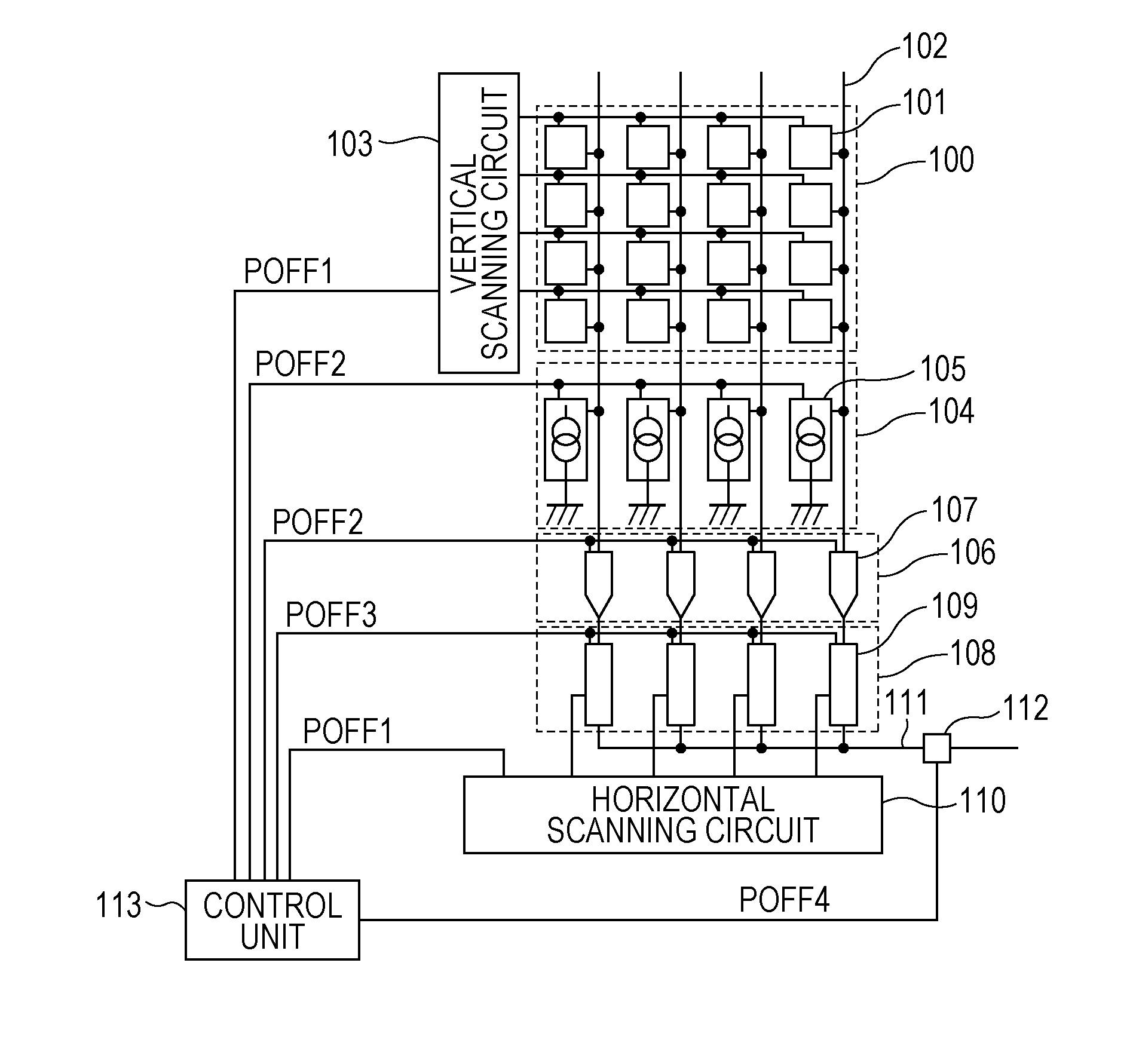
[0023]FIG. 1 is an overall block diagram of an image pickup apparatus according to a first embodiment.

[0024]A plurality of pixels 101 are arranged in an imaging area 100. The imaging area 100 here has a total of 16 pixels of 4 rows and 4 columns but may have more pixels. The configuration of the pixels 101 may vary. For example, what-is-called an APS sensor having a photoelectric conversion unit and a pixel amplifying unit which amplifies a signal generated in the photoelectric conversion unit may be used to improve its SN ratio.

[0025]The signals generated in the pixels 101 are output to a vertical signal lines 102 in response to a drive pulse from a vertical scanning circuit 103. For example, a drive pulse may be supplied to each row, and signals of a plurality of pixels included in the row are output to the corresponding vertical signal lines 102 in parallel. In FIG. 1, one vertical signal line 102 is provided for each pixel column. However, a plurality of vertical signal lines 10...

second embodiment

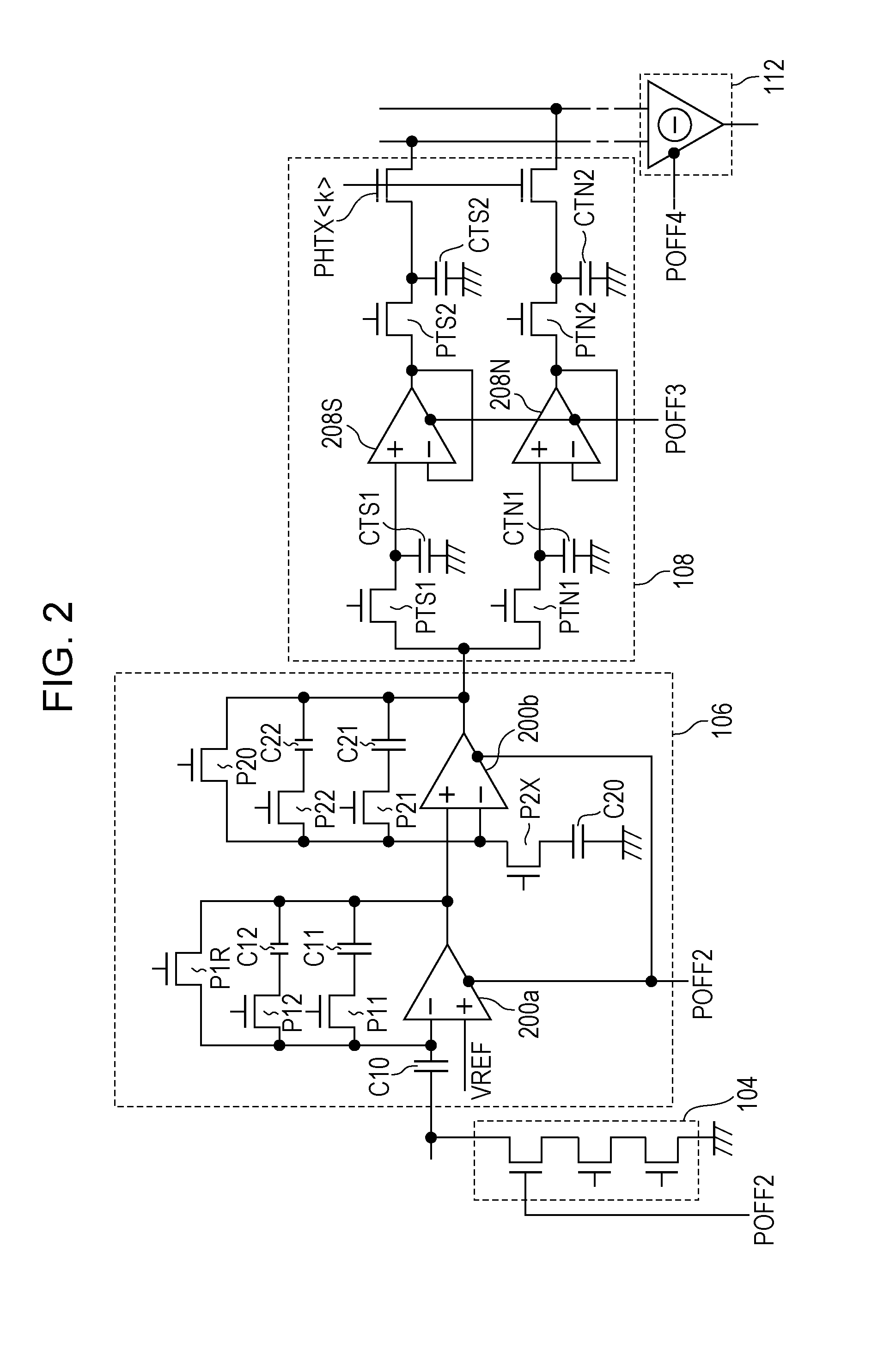
[0062]FIG. 6 is an equivalent circuit diagram of a column circuit in an image pickup apparatus of a second embodiment. This embodiment is different from the first embodiment in circuit configuration of the column circuit block 106. More specifically, a switch PXX and a switch P2R are added thereto. This configuration allows turning off the switch PXX and resetting the amplifier circuit 200a in the previous stage and the amplifier circuit 200b in the subsequent stage at independent times. This operation may reduce the resetting period and reduce a reading period.

[0063]FIG. 7 illustrates drive pulses of this embodiment. The basic drive sequence is the same as those in FIGS. 4 and 5. Except for the added control pulse PXX and control pulse P2R, the control pulses POFF2 to POFF4 for mode switching may be controlled in the same timing as the first embodiment.

third embodiment

[0064]FIG. 8 illustrates an overall block diagram of an image pickup apparatus according to a third embodiment. FIG. 9 illustrates an equivalent circuit diagram of a column circuit of this embodiment. Like numerals refer to components having like functions to those in the first embodiment, and the detail descriptions will be omitted.

[0065]This embodiment is different from the first and second embodiments in control pulses to be supplied to circuit blocks for mode switching. According to this embodiment, a control pulse POFF5 is supplied to all circuit blocks, and control pulses POFF6 to POFF8 are supplied to the circuit blocks. The control pulse POFF5 may be supplied to the circuit blocks during a period when signals are stored in the pixels 101, for example. During the period while the pixels 101 are storing signals, the circuit blocks may not be required to perform operations. Thus, during this period, the circuit blocks are switched to the second mode in response to the control p...


PUM


Abstract

An embodiment of an image pickup apparatus according to the present invention includes, on a semiconductor substrate, an imaging area having a plurality of pixel columns and a plurality of column circuits each of which is provided for each pixel column or a plurality of pixel columns. Each of the column circuits has a first circuit block and a second circuit block, and the first and second circuit blocks receive a bias voltage via a common wire. The first circuit block includes an amplifier circuit. The second circuit block is configured to be capable of switching between a first mode and a second mode with smaller power consumption than the first mode. A shift period from the second mode to the first mode by the second circuit block is a period excluding a period during which an amplifier circuit in the first circuit block is performing an amplifying operation.

Description

BACKGROUND OF THE INVENTION[0001]1. Field of the Invention[0002]The present invention relates to image pickup apparatuses and particularly relates to reduction of power consumption.[0003]2. Description of the Related Art[0004]A solid-state image pickup apparatus generally has an imaging area in which pixels are arranged in matrix form. A column circuit is provided for each pixel column or a plurality of pixel columns. The column circuit may be an amplifier circuit, a noise reduction circuit, an analog-digital converting circuit or the like. As an example of such a solid-state image pickup apparatus, a configuration disclosed in Japanese Patent Laid-Open No. 2009-224524 has been known.[0005]According to Japanese Patent Laid-Open No. 2009-224524, when a signal is transferred from a pixel to one hold capacitor of two hold capacitors which stores or holds signals transmitted at different times via column signal lines, the changes in potential of a reference power supply electrode in the...

Claims


Application Information

Patent Timeline
IPC IPC(8): H04N5/369
CPCH04N5/357H04N5/3698H04N25/60H04N25/709
Inventor YAMASHITA, YUICHIROMATSUDA, TAKASHI
Owner CANON KK
Why Eureka
Try Eureka