Liquid crystal display device and its driving method
- Summary
- Abstract
- Description
- Claims
- Application Information
AI Technical Summary
Benefits of technology
Problems solved by technology
Method used
Image

Examples
first embodiment
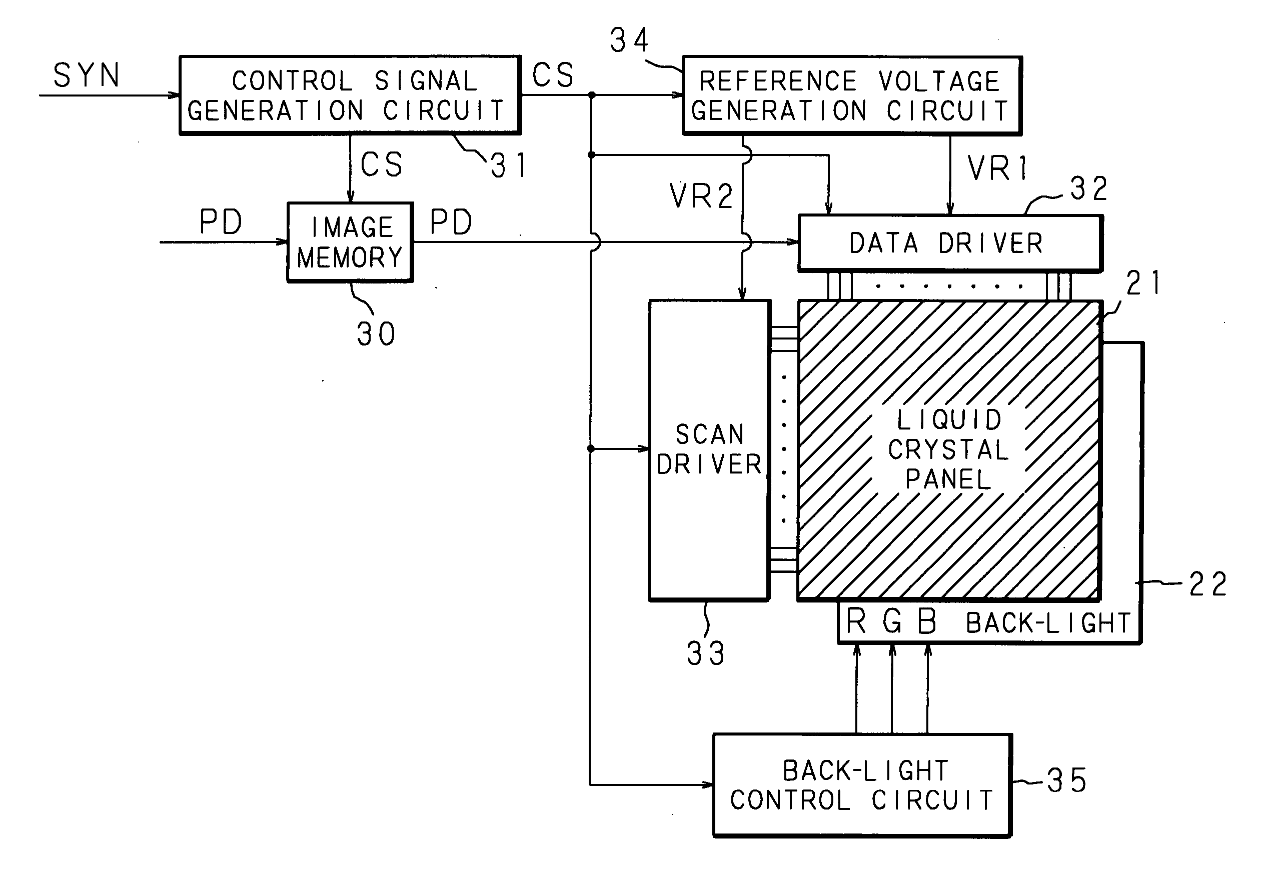
[0073]FIG. 3 is a block diagram showing the circuit structure of a liquid crystal display device according to the first embodiment of the present invention. FIG. 4 is a schematic cross sectional view of a liquid crystal panel and a back-light. And, FIG. 5 is a diagrammatic view showing the overall structure of the liquid crystal display device. The first embodiment is the liquid crystal display device that carries out a color displaying by using a field sequential method.
[0074] In FIG. 3, the numerals 21, 22 represent a liquid crystal panel and a back-light whose sectional structures are shown in FIG. 4. The back-light 22 is composed of an LED array 7 and a light guiding / diffusing plate 6, as shown in FIG. 4. As shown in FIG. 4 and FIG. 5, the liquid crystal panel 21 is configured such that a polarization film 1, a glass substrate 2, a common electrode 3, a glass substrate 4 and a polarization film 5 are stacked in this order from the upper layer (surface) side to the lower layer (...
example 1
[0084] After the TFT substrate having the pixel electrodes 40, 40 - - - (the number of the pixels of 640×480, the diagonal of 3.2 inches) and the glass substrate 2 having the common electrode 3 were washed, polyimide was coated, and they were baked at 200° C. for an hour. Consequently, polyimide films of about 200 Å were formed as the alignment films 11, 12. Moreover, those alignment films 11, 12 were rubbed with a cloth made of rayon, and those two substrates were stacked on each other so that the rubbing directions were parallel. Then, between both of them, they were stacked on each other in the situation that gap was held with the spacer 14 made of silica having an average particle diameter of 1.6 μm, and an empty panel was produced. A ferroelectric liquid crystal material (for example, a material disclosed in A. Mochizuki et al. Ferroelectrics, 133,353 (1991)) whose main component was a naphthalene-based liquid crystal indicating an electro-optic response characteristic of a hal...
example 2
[0090] After the TFT substrate having the pixel electrodes 40, 40 - - - (the number of the pixels of 640×480, the diagonal of 3.2 inches) and the glass substrate 2 having the common electrode 3 were washed, the polyimide was coated, and they were baked at 200° C. for an hour. Consequently, the polyimide films of about 200 Å were formed as the alignment films 11, 12. Moreover, those alignment films 11, 12 were rubbed with the cloth made of rayon, and those two substrates were stacked on each other so that the rubbing directions were parallel. Then, between both of them, they were stacked on each other in the situation that the gap was held with the spacer 14 made of the silica having the average particle diameter of 1.6 μm, and the empty panel was produced. A ferroelectric liquid crystal material of a mono-stable type (made by Clariant Japan: R2301) indicating the electro-optic response characteristic of the half-V-shape shown in FIG. 6 was sealed between those alignment films 11, 12...
PUM
 Abstract
Description
Claims
Application Information
 - R&D
- Intellectual Property
- Life Sciences
- Materials
- Tech Scout
- Unparalleled Data Quality
- Higher Quality Content
- 60% Fewer Hallucinations
Browse by: Latest US Patents, China's latest patents, Technical Efficacy Thesaurus, Application Domain, Technology Topic, Popular Technical Reports.
© 2025 PatSnap. All rights reserved.Legal|Privacy policy|Modern Slavery Act Transparency Statement|Sitemap|About US| Contact US: help@patsnap.com