
System for controlling HVAC and lighting functionality

a technology for lighting functionality and hvac, which is applied in the field of system for controlling hvac and lighting functionality, can solve the problems of high installation cost, rare energy savings realized from using the system to cover the cost of installation, and the cost of building control system installation includes equipment and time and labor

Active Publication Date: 2013-09-19
GROHMAN WOJCIECH MACIEJ
View PDF12 Cites 161 Cited by
  • Summary
  • Abstract
  • Description
  • Claims
  • Application Information

AI Technical Summary

Benefits of technology

This patent takes a new approach to make it easier to install a system using a configuration panel of occupancy detectors. The technical effect of this is that it makes it easier to set up and install the system, which can save time and make it more user-friendly.

Problems solved by technology

These systems allow for certain potential energy savings or improved comfort for building occupants, however their installation is costly and rarely do the energy savings realized from using the systems cover the cost of their installation.
The cost of installation of building control systems includes cost of the equipment as well as the time and labor involved in the physical installation.
While the cost of the equipment can be controlled, the time and labor are often unpredictable as they can vary significantly from one building to another.
These labor-related costs are the primary driver of the total system installation cost for many buildings.
Complexity of such installation adds significantly to the overall cost of the system deployment.
Likewise the maintenance of a complicated system requires additional labor further adding to the total cost of ownership for the system.

Method used


Image

  • System for controlling HVAC and lighting functionality
  • System for controlling HVAC and lighting functionality
  • System for controlling HVAC and lighting functionality

Examples


Embodiment Construction

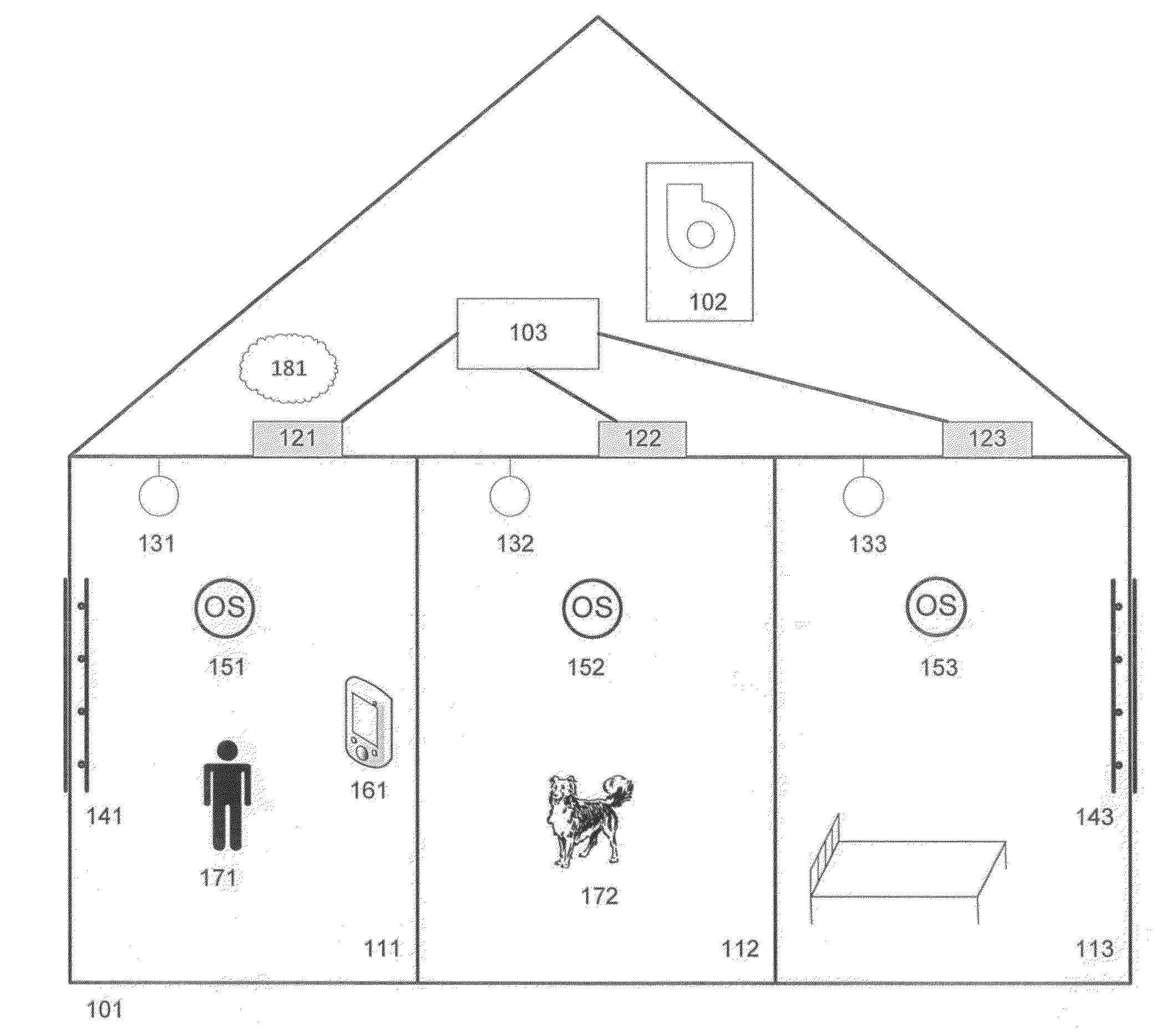
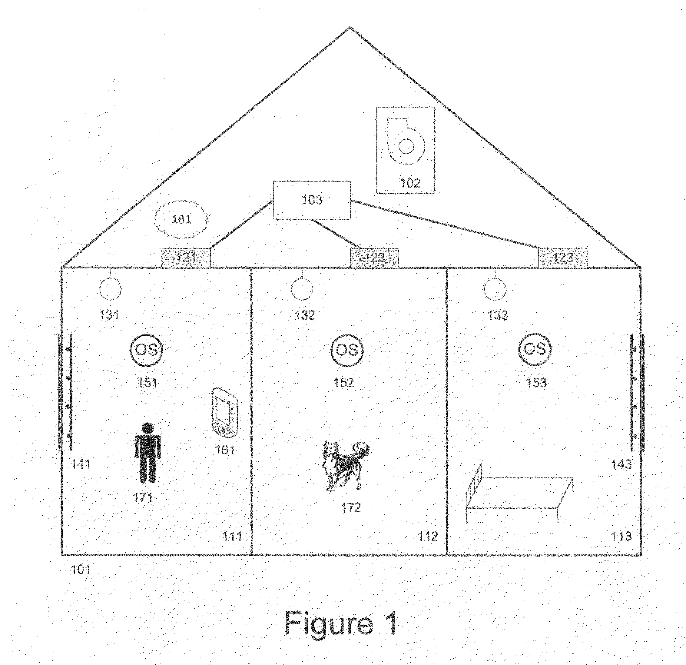
[0021]The FIG. 1 illustrates an embodiment of a system of the disclosure in a building 101. The building is equipped with the furnace 102 and / or other HVAC conditioning equipment, as well as the zoning panel 103 controlling conditioning in various rooms. The building contains different rooms or building zones 111, 112, and 113. In the illustrative non-limiting embodiment room 112 is a kitchen and room 113 is a bedroom. Shown are air vents or dampers 121, 122, and 123, corresponding to the respective room numbers 111, 112, and 113. Likewise, shown are light fixtures 131, 132, 133 and shade controllers 141 and 143.

[0022]Further shown are the occupancy sensors 151, 152, and 153. These are often battery powered and wireless to lower the installation and maintenance costs. A system user interface 161 facilitates the input to the system controller 181. The user interface is used to interact with the system and could be a shared resource with another control system in the building, such as...


PUM


Abstract

A system for automatic setup and control of Lighting, Heating Ventilation and Air Conditioning systems comprising a set of occupancy detectors and at least one controller where the controller determines various aspects of the building control based on the input of the occupancy detectors.

Description

RELATED APPLICATIONS[0001]This application claims benefit of and priority to Provisional Patent Application No. 61 / 685,505, filed Mar. 19, 2012, incorporated by reference herein.TECHNICAL FIELD[0002]This application is directed, in general, to systems and methods for managing operation of lighting, automatic shade and window control and heating, ventilation and air conditioning systems.BACKGROUND[0003]Most of today's buildings are lit up, and uniformly conditioned regardless of the state of occupancy in each part of the building. The modern occupancy control systems try to address the issue by allowing controlling of conditioning in only the rooms that are occupied. These systems allow for certain potential energy savings or improved comfort for building occupants, however their installation is costly and rarely do the energy savings realized from using the systems cover the cost of their installation. To be truly effective, a system has to be as inexpensive as possible, while provi...

Claims


Application Information

Patent Timeline
Patent Type & Authority Applications(United States)
IPC IPC(8): G05D23/19
CPCG05B15/00G05D23/19F24F2011/0075F24F2011/0064F24F11/0034F24F11/30F24F2120/10F24F11/62F24F11/64F24F11/65F24F11/46Y02B20/40G05B15/02H05B47/11G05B17/02G05B19/0428G05B2219/2614
Inventor GROHMAN, WOJCIECH MACIEJ
Owner GROHMAN WOJCIECH MACIEJ
Learn More