
Electromagnetic relay

Active Publication Date: 2013-09-19
ORMON CORP
View PDF2 Cites 4 Cited by
  • Summary
  • Abstract
  • Description
  • Claims
  • Application Information

AI Technical Summary

Benefits of technology

The present invention aims to provide an electromagnetic relay that can effectively dissipate the heat generated from the coil to secure desired attracting force even when the relay is miniaturized. The invention achieves this by increasing the surface area of the movable contact piece in the portion where it comes in contact with the movable iron piece, allowing for more efficient dissipation of heat generated from the coil. This prevents deterioration in the operating characteristic of the relay caused by temperature increase. Additionally, the invention increases the range where the movable contact piece is arranged, avoiding material punching waste and suppressing cost increase. Overall, the invention ensures desired operating characteristics of the electromagnetic relay.

Problems solved by technology

In this case, when the movable contact piece is decreased in the width and the surface area as described above, the heat generated from the coil may not be sufficiently discharged to the outside.
As a result, it is difficult to secure the desired attracting force of the electromagnet, which makes it difficult to miniaturize the conventional electromagnetic relay.

Method used


Image

  • Electromagnetic relay
  • Electromagnetic relay
  • Electromagnetic relay

Examples


Embodiment Construction

[0023]Hereinafter, preferred embodiments of the present invention will be described with reference to the drawings. Note that in the description below, terms that refer to specific directions and positions (for example, terms including “upper”, “lower”, “side”, and “end”) are used if necessary. The purpose of using those terms is to help one better understand the present invention referring to the drawings, but the technical scope of the present invention should not be limited by meanings of those terms. The description made hereinbelow represents just an essential example of the present invention and is not intended to limit the present invention, applications of the present invention, and uses of the present invention.

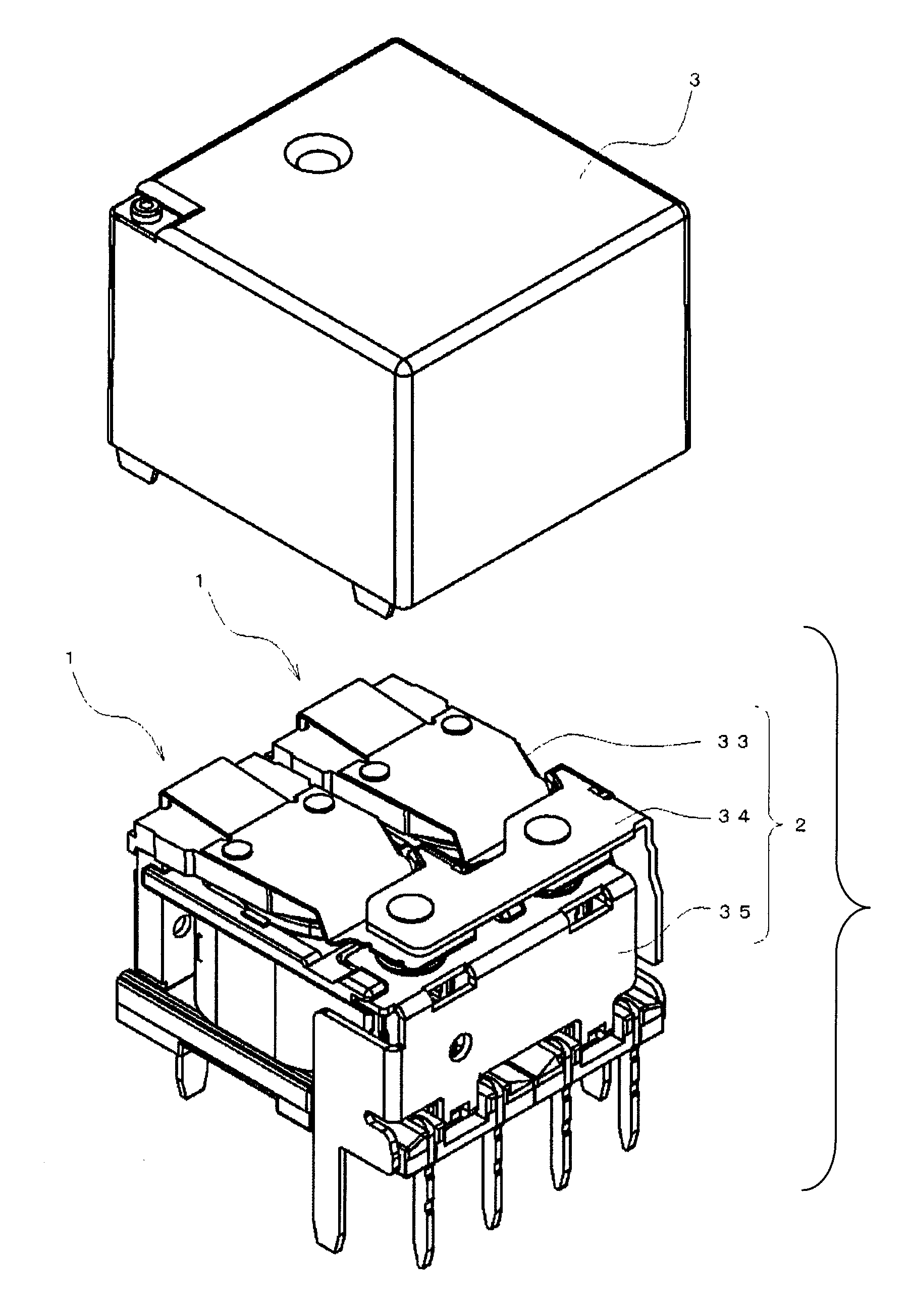
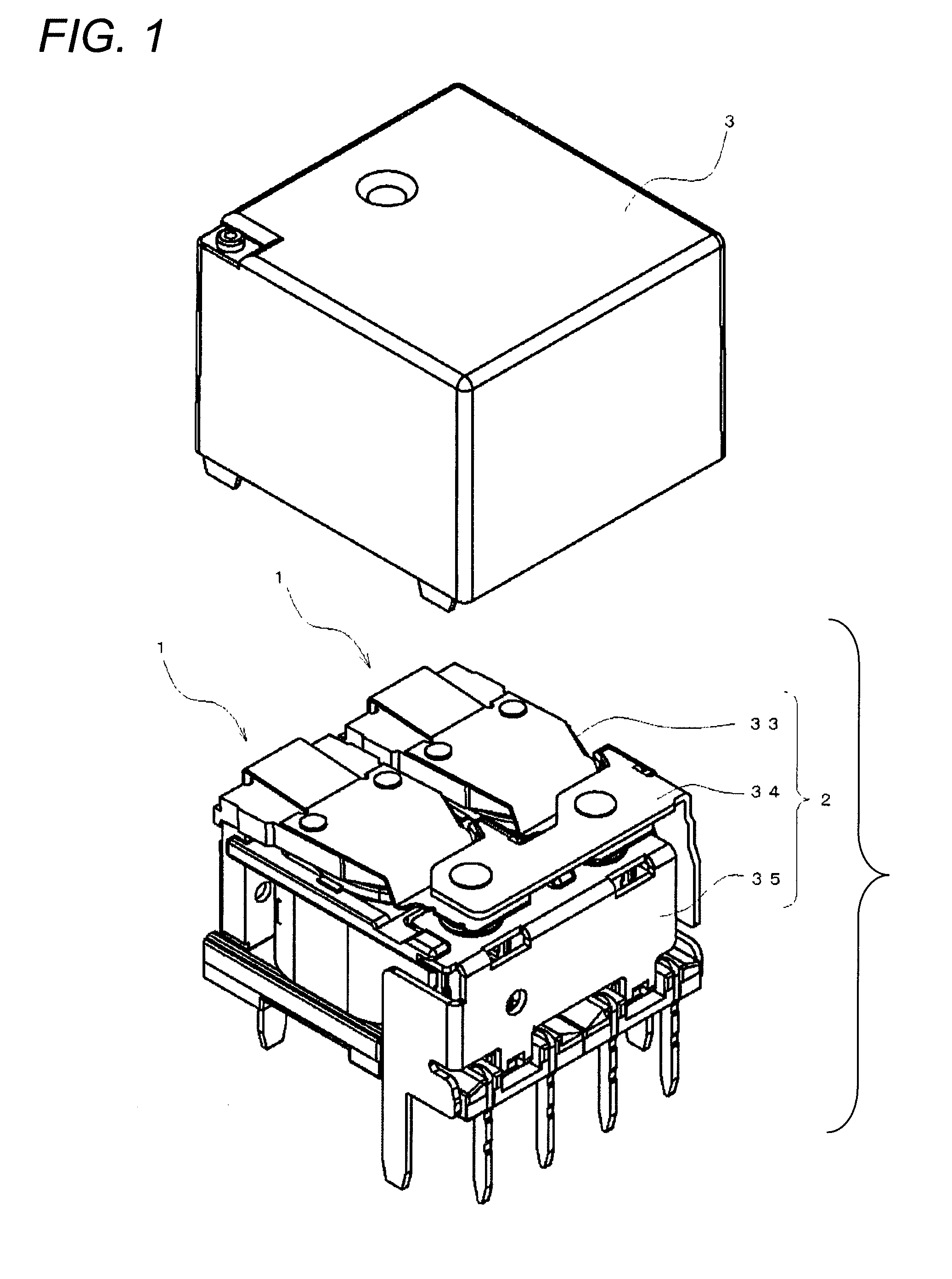
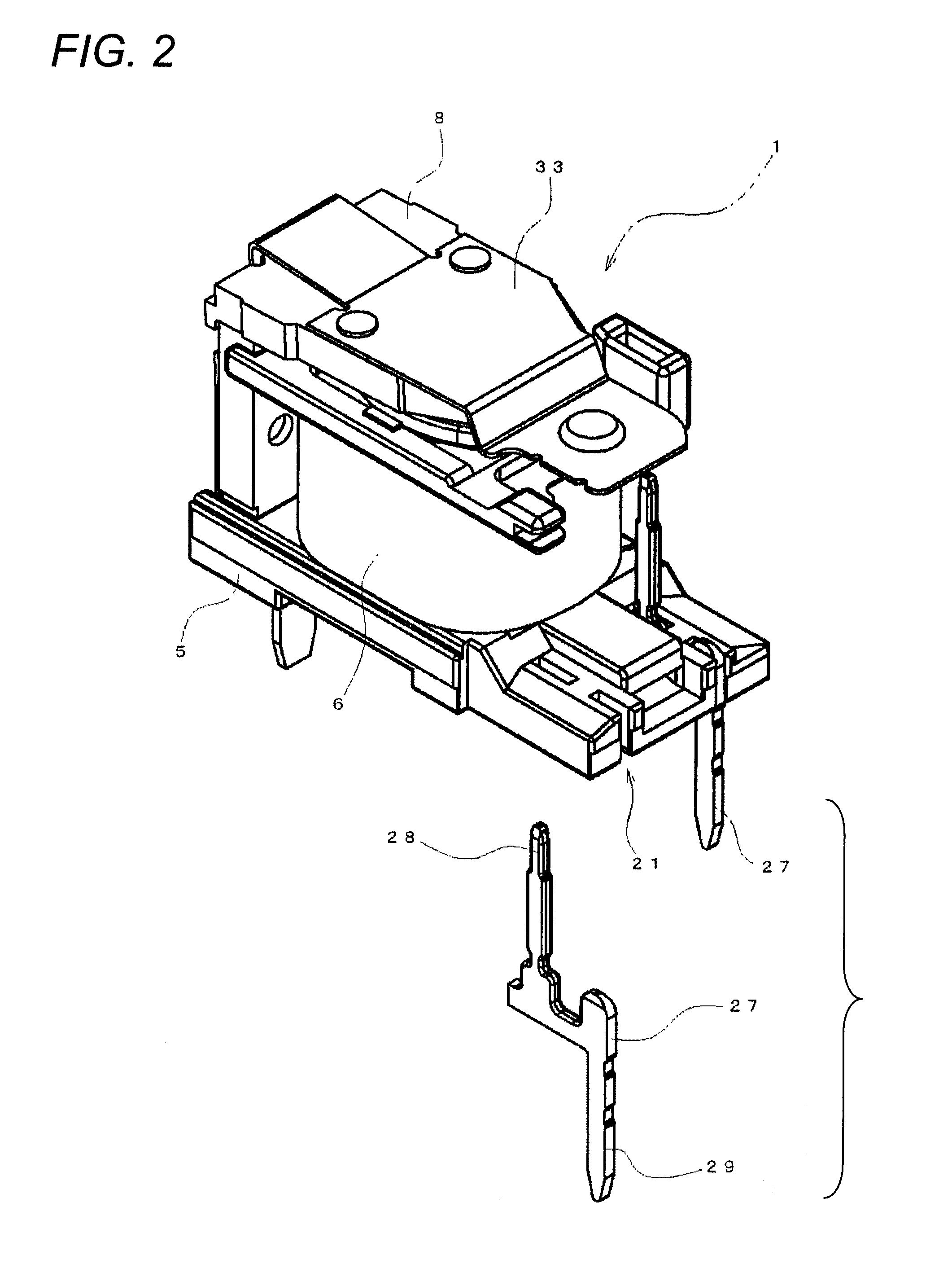
[0024]FIG. 1 illustrates an electromagnetic relay according to an embodiment of the present invention. This electromagnetic relay is configured such that one pair of electromagnet blocks 1 are provided side by side, a contact switching mechanism 2 is provided, and th...


PUM


Abstract

Provided is an electromagnetic relay which can sufficiently dissipate heat generated from a coil to secure desired attracting force even when the electromagnetic relay is miniaturized. The electromagnetic relay includes an electromagnet block and a contact switching mechanism. A movable contact piece of the contact switching mechanism includes a contact attaching portion to which a movable contact is attached, and a first fixed portion attached to a first movable iron piece of the electromagnet block. The first fixed portion is in surface contact with the movable iron piece and is substantially equal in width dimension to the movable iron piece.

Description

TECHNICAL FIELD[0001]The present invention relates to an electromagnetic relay.RELATED ART[0002]Conventionally, as an electromagnetic relay, there is known an electromagnetic relay having a configuration in which a fixed terminal is latched and attached to each spool of each electromagnet block in a press-fitted manner and each flange is connected in parallel to each other so that the electromagnet blocks may be integrally combined (see, for example, Japanese Unexamined Patent Publication No. 2000-315448).[0003]However, in such a conventional electromagnetic relay, when the electromagnetic relay is miniaturized, a movable contact piece needs to be reduced in width dimension because of its structural characteristic. This also brings about the reduction in size of the electromagnet. Accordingly, in order to secure the same magnitude of attracting force with the electromagnet of the reduced size, it is necessary to increase the energizing amount flowing to a coil. For this reason, the ...

Claims


Application Information

Patent Timeline
IPC IPC(8): H01H45/12
CPCH01H45/12H01H51/20H01H50/60H01H50/58
Inventor KOBAYASHI, MASAKI
Owner ORMON CORP
Learn More