
Touch panel

a touch panel and capacitance technology, applied in the field of capacitance touch panel, to achieve the effect of favorable touch sensing quality, increased capacitance coupling between the electrodes, and improved sensitivity of the touch panel

Active Publication Date: 2013-09-19
HTC CORP
View PDF15 Cites 12 Cited by
  • Summary
  • Abstract
  • Description
  • Claims
  • Application Information

AI Technical Summary

Benefits of technology

The patent improves the sensitivity and quality of touch panels by increasing the coupling capacitance between electrodes. This is achieved by placing two electrode patterns in the first and second openings of the electrode line. This results in a more favorable touch experience for users.

Problems solved by technology

Thus, how to improve the coupling capacitance and provide a good touch sensing quality to users is definitely an issue worth for further discussion.

Method used


Image

  • Touch panel
  • Touch panel
  • Touch panel

Examples


Embodiment Construction

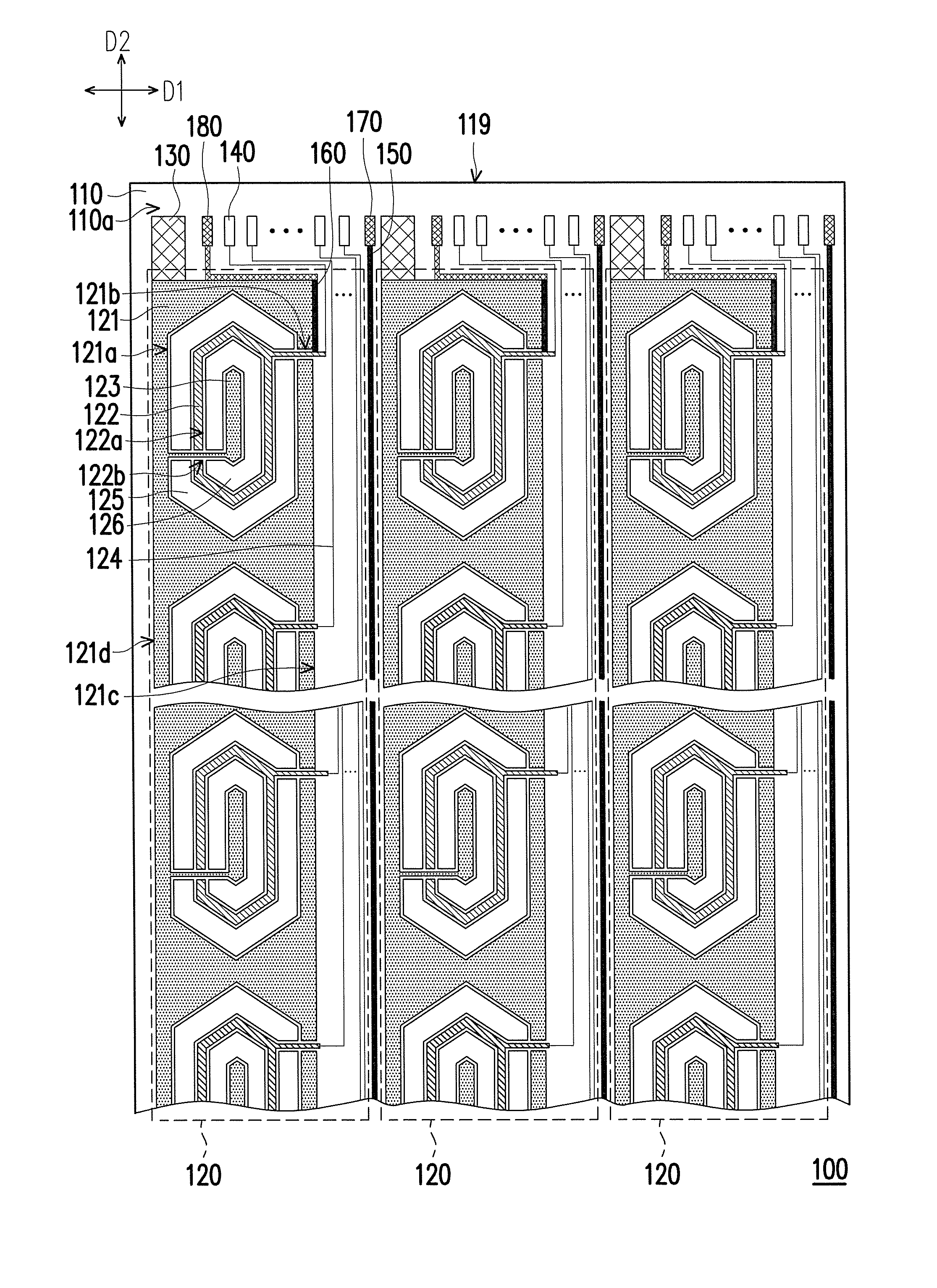
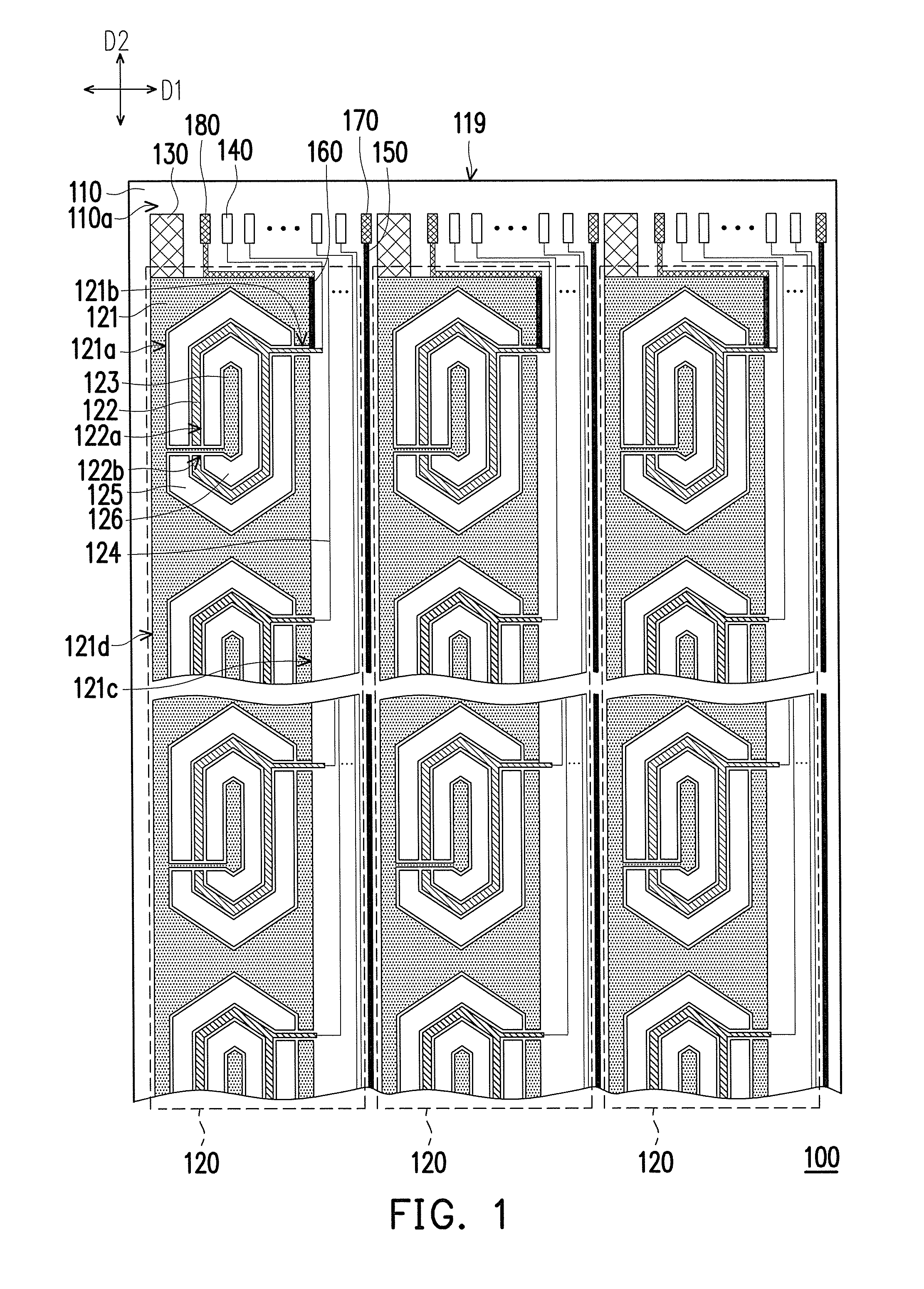
[0016]FIG. 1 is a schematic view of a touch panel according to an exemplary embodiment of the application. The touch panel 100 includes a substrate 110 and a plurality of sensing units 120. The substrate 110 has a surface 110a, and the sensing units 120 are arranged in parallel along a first direction D1 on the surface 110a. Each of the sensing units 120 includes an electrode line 121, a plurality of first electrode patterns 122, a plurality of second electrode patterns 123 and a plurality of connecting lines 124. The electrode line 121 extends along a second direction D2, and the first direction D1 intersects the second direction D2. In the embodiment, the touch panel 100 including three sensing units 120 is taken as an example for illustration, but the application is not limited thereto. Those skilled in the art can properly adjust the quantity of the sensing units 120 according to actual requirements.

[0017]As shown in FIG. 1, the electrode line 121 has a plurality of first openin...


PUM


Abstract

A touch panel includes a substrate and sensing units. Each sensing unit includes an electrode line, first electrode patterns, second electrode patterns and connecting lines. The electrode line extends along a second direction and has first openings arranged along the second direction and first breaches corresponding to the first openings. Each first breach connects the corresponding first opening and the exterior of the electrode line. The first electrode patterns are respectively disposed in the first openings. Each first electrode pattern has a second opening and a second breach connecting the second opening and the exterior of first electrode pattern. The second electrode patterns are respectively disposed in the second openings and respectively connected with the electrode line through the second breaches. The connecting lines are disposed on at least one side of the electrode line and connected with the corresponding first electrode pattern through the first breach.

Description

CROSS-REFERENCE TO RELATED APPLICATION[0001]This application claims the priority benefits of U.S. provisional application Ser. No. 61 / 611,005, filed on Mar. 14, 2012. The entirety of the above-mentioned patent application is hereby incorporated by reference herein and made a part of this specification.BACKGROUND OF THE APPLICATION[0002]1. Field of the Application[0003]The application relates to a touch panel, and more particularly, to a capacitive touch panel.[0004]2. Description of Related Art[0005]As information technology, wireless mobile communication and information appliances have been rapidly developed and applied, to achieve more convenience, more small volume, light weight and more user-friendly designs, various information products have changed from using conventional input devices such as key boards or mice to using touch panels.[0006]Based on different sensing types, touch panels can be categorized into resistive touch panels, capacitive touch panels, optical touch panel...

Claims


Application Information

Patent Timeline
Patent Type & Authority Applications(United States)
IPC IPC(8): H03K17/96
CPCH03K17/9622G06F3/044G06F3/04164G06F3/0443G06F3/0448
Inventor LO, PI-LINLIN, YEN-CHENGHSUEH, YI-FANCHEN, TE-MU
Owner HTC CORP
Learn More