
Method for fabricating semiconductor device with porous dielectric structure

a technology of dielectric structure and semiconductor device, which is applied in the direction of semiconductor devices, basic electric elements, electrical appliances, etc., can solve the problems of constant increase in quantity and complexity, and achieve the reduction of rc delay of semiconductor devices, reducing operating current consumption of semiconductor devices, and reducing the coupling capacitance between the gate structure and the source/drain region.

Pending Publication Date: 2022-02-24
NAN YA TECH
View PDF5 Cites 0 Cited by
  • Summary
  • Abstract
  • Description
  • Claims
  • Application Information

AI Technical Summary

Benefits of technology

The semiconductor device of this patent design reduces the coupling capacitance between the gate structure and the source / drain regions, which decreases the RC delay of the device. Additionally, the presence of a covering layer helps to reduce operating current consumption.

Problems solved by technology

However, a variety of issues arise during the down-scaling process, and such issues are continuously increasing in quantity and complexity.
Therefore, challenges remain in achieving improved quality, yield, performance, and reliability and reduced complexity.

Method used


Image

  • Method for fabricating semiconductor device with porous dielectric structure
  • Method for fabricating semiconductor device with porous dielectric structure
  • Method for fabricating semiconductor device with porous dielectric structure

Examples


Embodiment Construction

[0047]The following disclosure provides many different embodiments, or examples, for implementing different features of the provided subject matter. Specific examples of components and arrangements are described below to simplify the present disclosure. These are, of course, merely examples and are not intended to be limiting. For example, the formation of a first feature over or on a second feature in the description that follows may include embodiments in which the first and second features are formed in direct contact, and may also include embodiments in which additional features may be formed between the first and second features, such that the first and second features may not be in direct contact. In addition, the present disclosure may repeat reference numerals and / or letters in the various examples. This repetition is for the purpose of simplicity and clarity and does not in itself dictate a relationship between the various embodiments and / or configurations discussed.

[0048]F...


PUM

PropertyMeasurementUnit
porosityaaaaaaaaaa
porosityaaaaaaaaaa
thicknessaaaaaaaaaa

Abstract

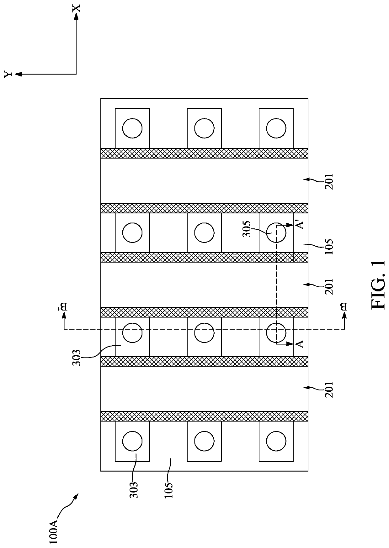
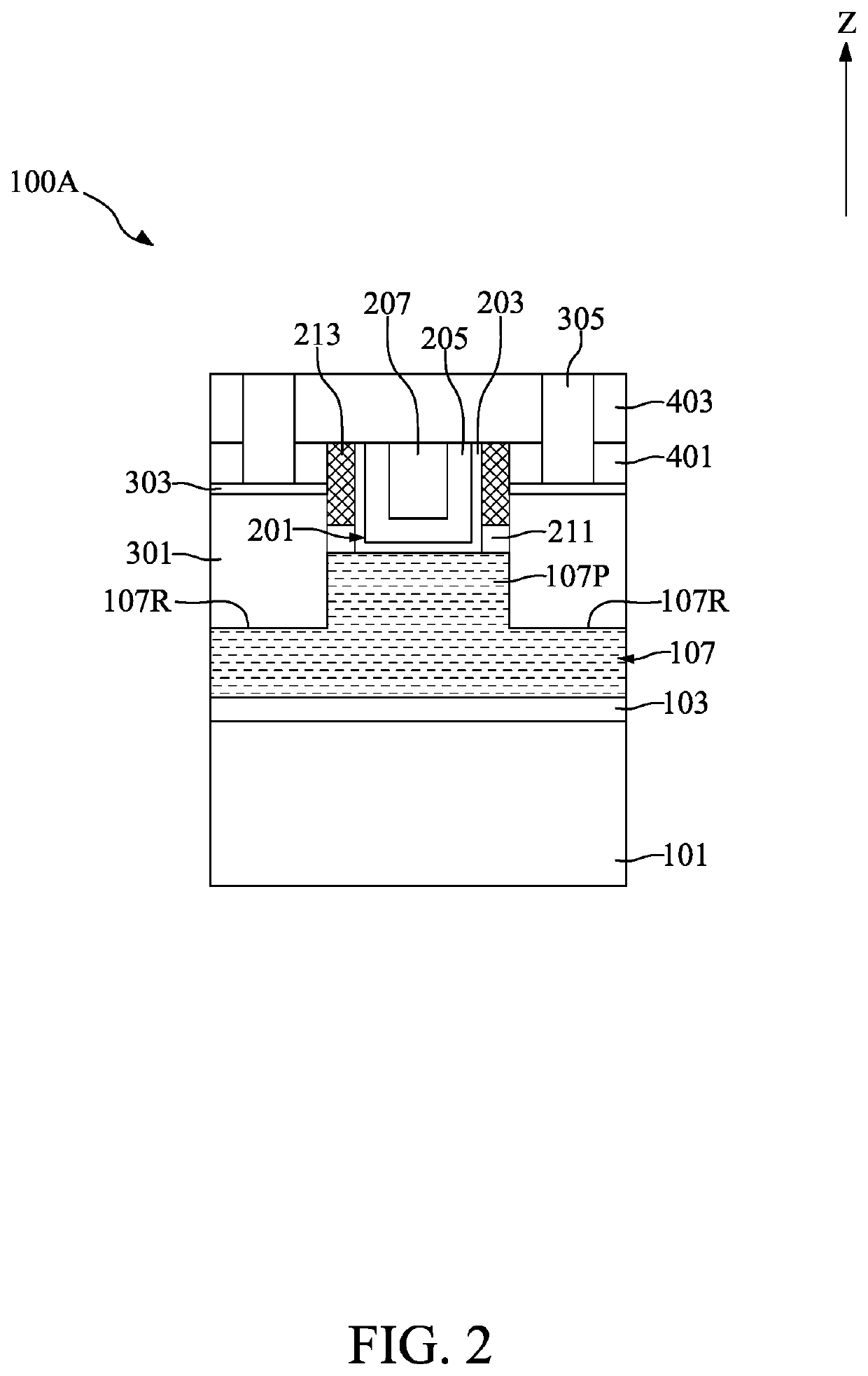
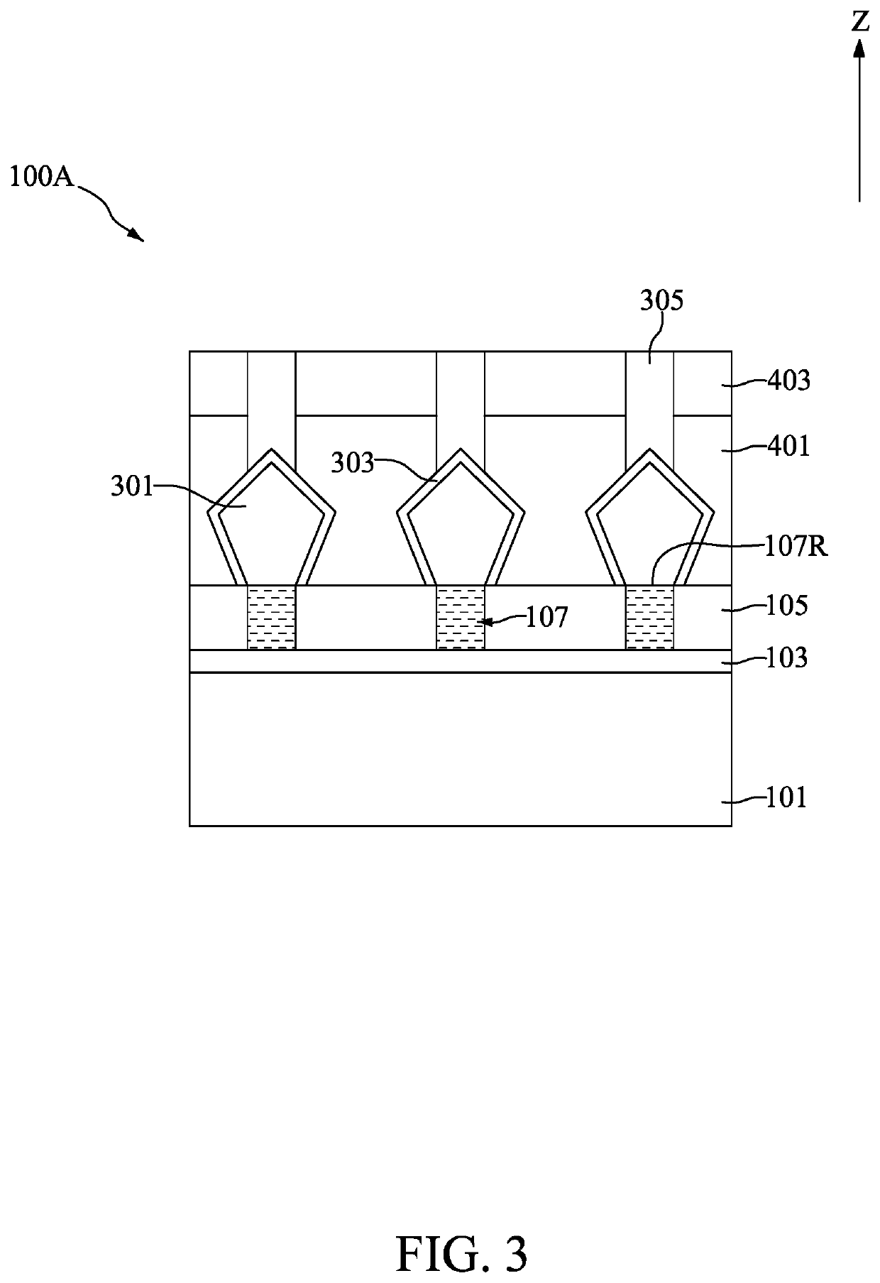
The present application discloses a method for fabricating a semiconductor device. The method includes providing a substrate; forming two conductive features apart from each other over the substrate; forming a porous middle layer positioned between the two conductive features and adjacent to the two conductive features; depositing an energy-removable material between the two conductive features and adjacent to the two conductive features; and performing an energy treatment to transform the energy-removable material into a porous middle layer. The porosity of the porous middle layer is between about 25% and about 100%.

Description

CROSS-REFERENCE TO RELATED APPLICATION[0001]This application is a divisional application of U.S. Non-Provisional application Ser. No. 16 / 751,168 filed Jan. 23, 2020, which is incorporated herein by reference in its entirety.TECHNICAL FIELD[0002]The present disclosure relates to a method for fabricating a semiconductor device, and more particularly, to a method for fabricating a semiconductor device with the porous structure.DISCUSSION OF THE BACKGROUND[0003]Semiconductor devices are used in a variety of electronic applications, such as personal computers, cellular telephones, digital cameras, and other electronic equipment. The dimensions of semiconductor devices are continuously being scaled down to meet the increasing demand of computing ability. However, a variety of issues arise during the down-scaling process, and such issues are continuously increasing in quantity and complexity. Therefore, challenges remain in achieving improved quality, yield, performance, and reliability an...

Claims


Application Information

Patent Timeline
Patent Type & Authority Applications(United States)
IPC IPC(8): H01L29/78H01L29/66H01L29/417H01L29/49
CPCH01L29/785H01L29/4991H01L29/41791H01L29/6681H01L27/0886H01L21/823431H01L29/66795H01L21/02203
Inventor TSAI, HUNG-CHI
Owner NAN YA TECH
Learn More