Flow rate compensation for transient thermal response of hot-wire anemometers

a technology of flow rate compensation and hot-wire anemometer, which is applied in the direction of instruments, liquid/fluent solid measurement, operating means/releasing devices of valves, etc., can solve the problems of imbalance in the bridge, and the inability to adjust the flow rate, so as to increase or decrease the flow rate. , the electronic temperature controller takes a long time (transient period) to respond and increase or decreas

Active Publication Date: 2013-09-19
COVIDIEN LP
View PDF4 Cites 27 Cited by
  • Summary
  • Abstract
  • Description
  • Claims
  • Application Information

AI Technical Summary

Benefits of technology

The patent describes a system and method for compensating for changes in the temperature of a hot-wire anemometer used in a medical ventilator. The compensation is based on the fraction of inspired oxygen (FiO2) being supplied to the patient by the ventilator. The method involves receiving an output signal from the flow sensor, which is indicative of the rate of flow of expired gas by the patient. A corrective modification is applied to the output signal or a value based on the FiO2 setting change, the average flow rates through the flow sensor, and the dynamics of the temperature control circuit. This allows for accurate measurement of the gas types being measured, even during changes in the gas concentration. The system can also transition between the expiratory and inspiratory phases of the ventilator based on the corrected output signal.

Problems solved by technology

Changes in certain properties of the gas passing by the filament impact the heat exchange between the filament and the gas flow, thus leading to a change in the filament's temperature.
Any deviation between the existing temperature and the reference temperature causes an imbalance in the bridge and the electronic control circuits respond by taking action to increase or decrease the current through the filament to adjust the temperature error.
Notably, however, it takes some time (transient period) for the electronic temperature controller to respond and increase or decrease the filament current to adjust to the reference temperature.

Method used


Image

  • Flow rate compensation for transient thermal response of hot-wire anemometers
  • Flow rate compensation for transient thermal response of hot-wire anemometers
  • Flow rate compensation for transient thermal response of hot-wire anemometers

Examples


Embodiment Construction

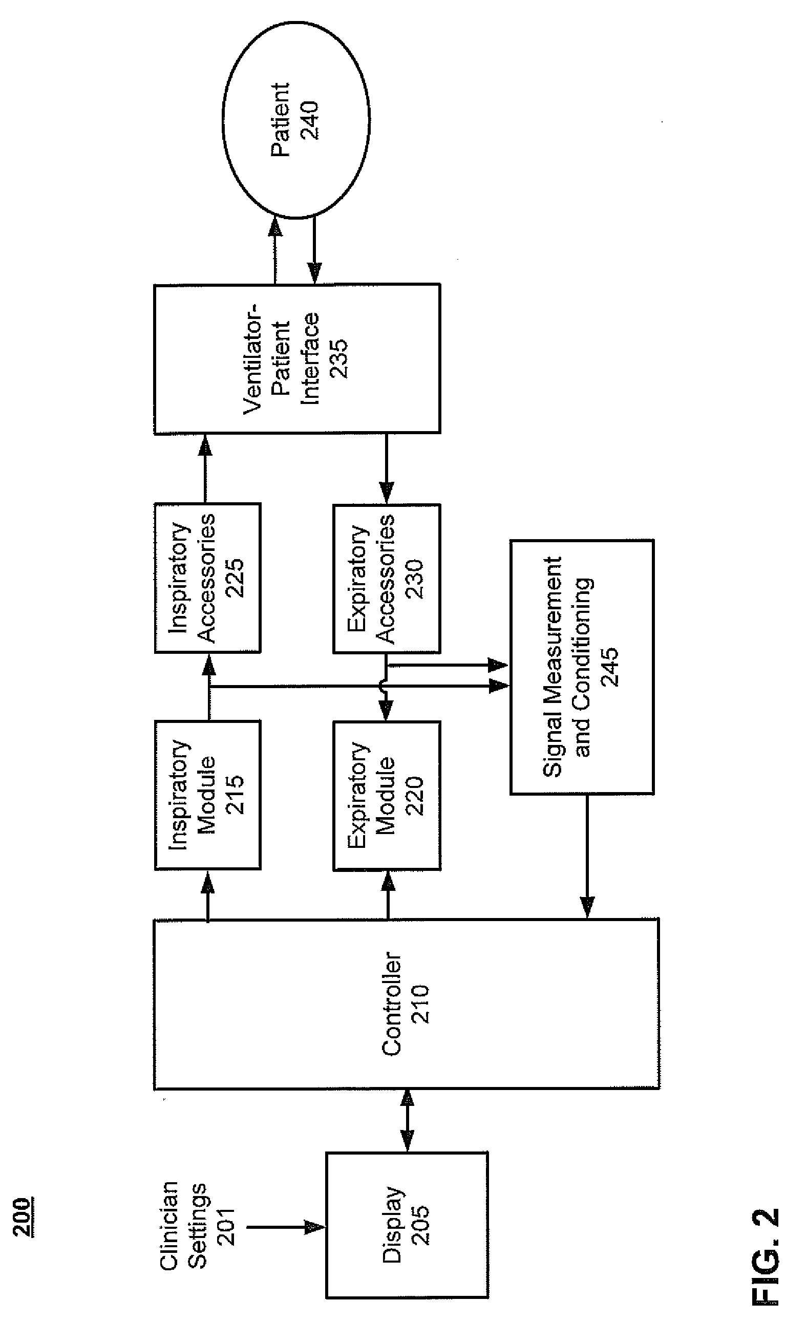
[0047]Systems and methods are described for application of a transitory corrective modification to a hot-wire anemometer flow voltage and / or calculated flow rate to compensate for transient thermal response of the anemometer during a change in mixture of a mixed gas being measured. Under steady state breathing gas conditions, approximation techniques to estimate the flow rate (and subsequently integrated volume) of exhaled gas passing through an exhalation hot-wire anemometer flow sensor are acceptable; however, it has been observed that upon a setting change in the desired fraction of inspired oxygen (FiO2), the reported exhaled tidal volumes demonstrate a transient behavior (i.e., increased reported volume for a setting decrease in desired oxygen concentration and decreased reported volume for a setting increase in desired oxygen concentration). This transient behavior lasts for a relatively short period of time (typically, less than 30 to 60 seconds) before the values stabilize t...


PUM


Abstract

Systems and methods are described for application of a transitory corrective modification to a hot-wire anemometer flow voltage and / or calculated flow rate to compensate for transient thermal response of the anemometer during a change in mixture of a mixed gas being measured. According to one embodiment a method of applying the transitory corrective modification is provided. An output signal of an exhalation flow sensor of a medical ventilator is received. The flow sensor includes a hot-wire anemometer. The output signal is indicative of a rate of flow of expired gas by a patient. Transient thermal response of the hot-wire anemometer is compensated for by applying a corrective modification to the output signal or a value based thereon. The corrective modification is based at least in part on a fraction of inspired oxygen (FiO2) being supplied by the medical ventilator to the patient.

Description

BACKGROUND[0001]1. Field[0002]Embodiments of the present invention generally relate to flow sensors, and more particularly to systems and methods for compensating for transient thermal response of hot-wire anemometers resulting from a change in the mixture of gas being measured.[0003]2. Description of the Related Art[0004]Many medical ventilators use hot-wire anemometer flow sensors to measure flow rates both at the input (inspiratory) and output (expiratory) ports. Hot-wire anemometers are usually calibrated for specific gases and calibration parametric values are different depending on the gas type (e.g., air or oxygen). On the inspiratory side of a medical ventilator, anemometers with single gas calibration (e.g., air or oxygen) may be used in the appropriate gas conduits; however, at the expiratory side, the mixture of gas passing through an exhalation flow sensor varies based on breath phase and other factors.[0005]Hot-wire anemometers operate with either constant current or co...

Claims


Application Information

Patent Timeline
Patent Type & Authority Applications(United States)
IPC IPC(8): A61M16/12A61M16/08A61M16/06A61M16/00
CPCA61M2016/0042G01F1/68G01F1/6965A61M16/12A61M16/06A61M16/0816A61M16/0875A61M16/0057
Inventor JAFARI, MEHDI M.JIMENEZ, RHOMERE S.MCCOY, EDWARD R.AVIANO, JEFFREY K.
Owner COVIDIEN LP
Why Eureka
Try Eureka