
Igniter base for pyrotechnic devices

Inactive Publication Date: 2013-09-19
A & O TECH
View PDF8 Cites 1 Cited by
  • Summary
  • Abstract
  • Description
  • Claims
  • Application Information

AI Technical Summary

Benefits of technology

The present invention aims to address the shortcomings of the current process of manufacturing pyrotechnic initiators. The invention proposes a new configuration that combines the benefits of a glass-to-metal seal and a plastic-to-metal seal for better protection against external influences and simplified construction of the ignition device. The invention also achieves a less expensive manufacture of the ignition base.

Problems solved by technology

The processes for this construction are very complex, in part because many expensive components are needed and in addition the number of manufacturing steps is high.
In particular, the welding of the metal cup with a metal ring proves to be not unproblematic, because a test for absolute leaktightness of such an igniter is possible only conditionally and only with considerable complexity.
This construction has the combination of a large number of different components with a corresponding number of working steps for its assembly, which is costly and from the viewpoint of production technology is complex.
This construction is also complex and therefore costly.
Thus few and in addition inexpensive supply materials are necessary for a reduced number of process steps.
Furthermore it is disadvantageous that, according to specifications usual today, round contact pins are required, which during insertion into an injection-molding die can be fixed only in longitudinal direction.
Thus the contact pin can be turned inside the die; if a bending or crimping of the contact pin or pins is then still necessary, the position of the contact pins can no longer be correctly controlled for fixing the bridge wire, so that an absolute reproducibility of the required arrangement is not given.
Once again metal and plastic behave very differently during this grinding, so that it cannot always be guaranteed that a clean and smooth surface is then achieved.

Method used


Image

  • Igniter base for pyrotechnic devices
  • Igniter base for pyrotechnic devices

Examples


Embodiment Construction

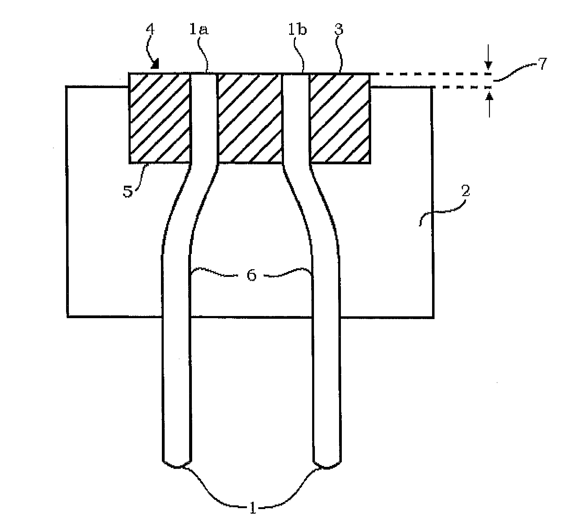
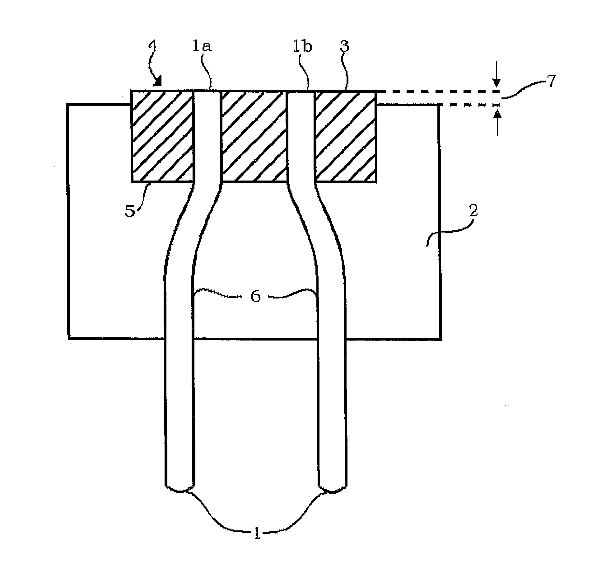
[0037]Two doubly crimped contact pins 1 are fused into a glass base 3 and at the end face 4 of the glass base 3 form a plane therewith. On the opposite side 5, the contact pins 1 project out of the glass base 3.

[0038]Below the end face 4, the glass base 3 and a part 6 of the contact pins 1 is overmolded with a plastic jacketing 2. The plastic overmolding or jacketing is offset or set back slightly 7 relative to the end face 4 of the glass base 3.

[0039]At the end face 4 of the glass base 3, the contact pins 1 form contact poles 1a and 1b respectively for the seat of an ignition bridge, not illustrated, which connects the poles galvanically. The ignition bridge can be both welded fusionally with the poles and also joined thereto by simple contact, in that it is held in galvanic contact with the poles by the solid ignition compound.

[0040]The plastic jacketing 2 permits both a hermetic joint with a container enclosing the pyrotechnical ignition compound and also an interface to the surr...


PUM


Abstract

Igniter base for a pyrotechnic initiator has a glass base together with fused-in contact pins that function as a pole carrier and thus fixes the contact pins in secure correlation to one another. The end side of the glass base and the contact pins form a level plane, so that an ignition bridge resting flush on the glass base can be attached to the poles. The contact pins project beyond the glass base on the opposite side and a part of the glass base and a part of the contact pins projecting beyond the glass base are equipped with a plastic jacketing.

Description

CROSS REFERENCE TO RELATED APPLICATIONS[0001]Applicant claims priority under 35 U.S.C. §119 of German Application No. 10 2012 004 966.8 filed Mar. 14, 2012, the disclosure of which is incorporated by reference.BACKGROUND OF THE INVENTION[0002]1. Field of the Invention[0003]Pyrotechnic initiators are needed in gas generators for passive safety systems such as airbags and belt tensioners in motor vehicles.[0004]Such gas generators work with initiators, by means of which a propellant charge can be ignited pyroelectrically.[0005]Such pyrotechnical devices guarantee a reliable ignition of the propellant charge and function flawlessly over many years. For this assignment, such devices must assure a function over decades.[0006]This condition requires that a flawless function is guaranteed permanently and that the igniter and also the propellant charge are not changed during the service time. It must be assured that, for example, no moisture can penetrate into the gas generator. For this as...

Claims


Application Information

Patent Timeline
IPC IPC(8): F42D1/05
CPCF42B3/12F42B3/107F42D1/05
Inventor KRAFT, ANDREKUHN, CHRISTIANJURKOWSKI, OLAF
Owner A & O TECH
Learn More