
Computer system, migration method, and management server

Inactive Publication Date: 2013-09-12
HITACHI LTD
View PDF4 Cites 30 Cited by
  • Summary
  • Abstract
  • Description
  • Claims
  • Application Information

AI Technical Summary

Benefits of technology

The invention allows for efficient use of computer resources by searching for a physical computer with a suitable amount of resources based on the demand of the virtual computer. Compared to using only the assigned resource, the virtual computer can be moved to a more suitable physical computer that has more resources available.

Problems solved by technology

However, in the conventional method, in such a case where a used resource amount of the virtual server device is small, even if a resource pool includes a resource amount equal to or more than the used resource amount, the resource pool is not selected as the migration destination.
As a result, an effective use of the resources is difficult.

Method used


Image

  • Computer system, migration method, and management server
  • Computer system, migration method, and management server
  • Computer system, migration method, and management server

Examples


first embodiment

[0045]In a first embodiment, a description is given of a virtualization technology by means of the VM method.

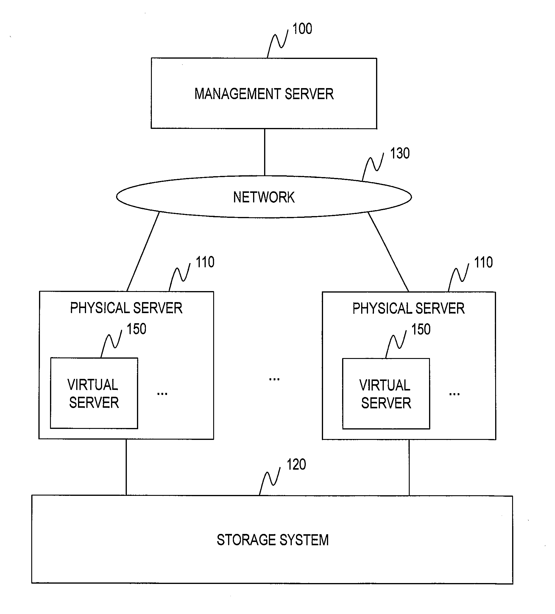
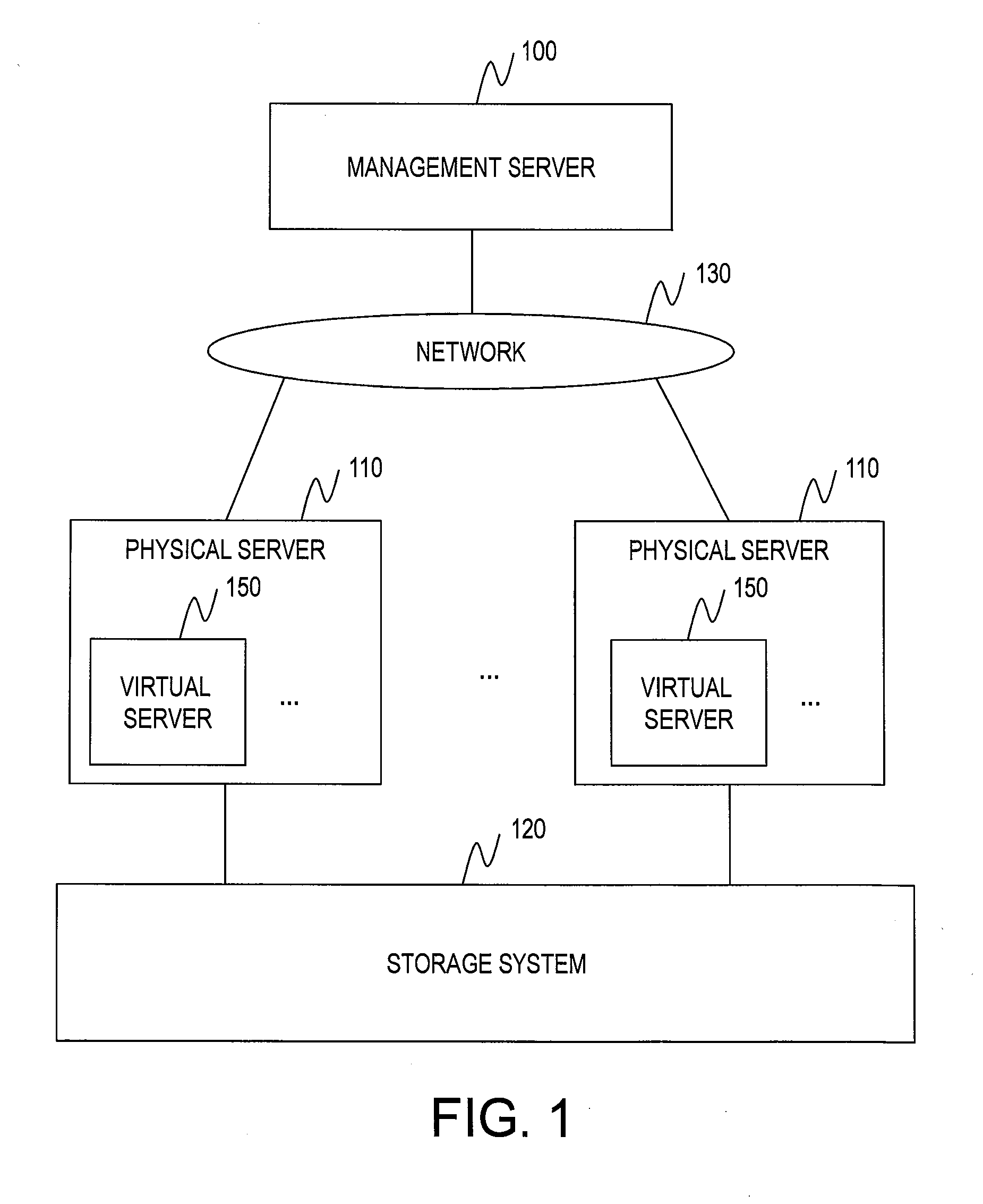
[0046]FIG. 1 is an explanatory diagram illustrating a configuration example of a computer system according to the first embodiment of this invention.

[0047]The computer system includes a management server 100, physical servers 110, and a storage system 120.

[0048]The management server 100 and the physical servers 110 are coupled to each other via a network 130. As the network 130, for example, a LAN, a WAN, or the like is conceivable.

[0049]Moreover, the physical servers 110 and the storage system 120 are coupled to each other directly or via a SAN or the like.

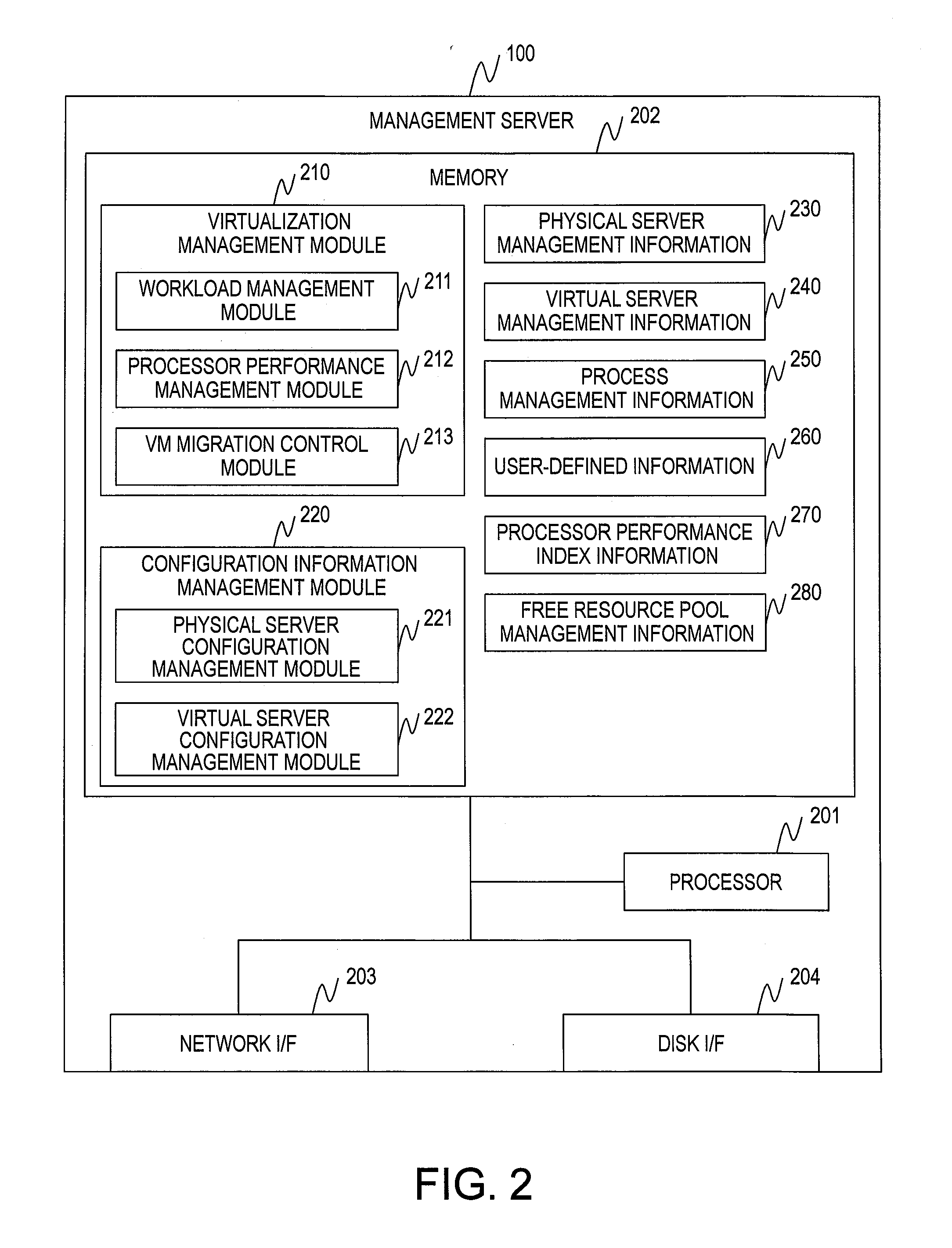
[0050]The management server 100 manages the entire computer system. A hardware configuration and a software configuration of the management server 100 are described later with reference to FIG. 2.

[0051]The physical server 110 is a computer on which virtual servers 150 operate so that a user provides a service. A hardware c...

second embodiment

[0352]In a second embodiment, a description is given of the LPAR method. It should be noted that differences from the first embodiment are mainly described.

[0353]Configurations of the computer system, the management server 100, the physical servers 110, and the storage system 120 according to the second embodiment are the same as those of the first embodiment, and a description thereof is therefore omitted.

[0354]The LPAR method is different in how to assign resources to the virtual servers 150.

[0355]FIG. 24 is an explanatory diagram illustrating a logical configuration of the computer system according to the second embodiment of this invention.

[0356]The virtualization module 310 logically divides the resources included in the physical server 110, and assigns an LPAR 2400 constituted by the logically divided resources to the virtual server 150.

[0357]In the example illustrated in FIG. 24, the LPAR 2400 includes a processor core 2410, a storage area 2420, and an LU 502. The resources a...


PUM


Abstract

A computer system, comprising: a plurality of physical computers; and a management server for managing the plurality of physical computers, wherein at least one virtual computer operates on each of the plurality of physical computers, wherein the at least one virtual computer executes at least one piece of service processing including at least one piece of sub processing, wherein the management server is configured to calculate a required resource amount which is a resource amount of a computer resource required for the virtual computer subject to the migration based on used resource amount for the each of the plurality of the pieces of sub processing; search for a physical computer of a migration destination; and migrate the virtual computer subject to the migration to the physical computer of the migration destination.

Description

BACKGROUND OF THE INVENTION[0001]This invention relates to a migration technology for migrating a virtual server operating on a physical server in a cloud environment.[0002]In the cloud environment, servers having different performances are mixed. For example, a server has a CPU high in clock frequency and a server has a CPU low in clock frequency are mixed. In a resource pool, a total value (total value of clock frequencies in the case of CPUs) of resource amounts included in the respective server devices included in the resource pool is managed as a resource amount of the resource pool.[0003]For example, a resource pool including four CPUs each being a clock frequency of 3 GHz, and a resource pool including six CPUs each being a clock frequency of 2 GHz both have a total value of the clock frequencies of 12 GHz, and are thus treated as resource pools having the same CPU resources.[0004]A user uses a virtual server device (VM) constructed by using the server device, thereby providi...

Claims


Application Information

Patent Timeline
IPC IPC(8): G06F9/48
CPCG06F9/5088G06F9/4856G06F2212/152G06F2009/4557G06F12/0223G06F9/45558
Inventor TANINO, MITSUHIROUCHIDA, TOMOHITO
Owner HITACHI LTD
Learn More