Ac-ac converter

a converter and ac technology, applied in the field of ac-ac converters, can solve the problems of inability to reduce loss, and achieve the effects of reducing switching loss, reducing inductors' size, and keeping the loss of rectifiers sufficiently small

Active Publication Date: 2013-09-12
FUJI ELECTRIC CO LTD
View PDF2 Cites 15 Cited by
  • Summary
  • Abstract
  • Description
  • Claims
  • Application Information

AI Technical Summary

Benefits of technology

[0013]The method of the heretofore known technology shown in PLT 1 is such that, although it is possible to reduce conduction loss in the first operation, switching loss is equivalent to that in the combination of the high power factor rectifier and inverter in which no bidirectional switch 11 is provided. Also, although the current passes through two reactors from the input until reaching the output in both the first and second operations, it is not possible to reduce loss occurring here.
[0014]Consequently, in order to solve the heretofore described kinds of problem, an object of the invention is to provide an AC-AC converter such that it is possible to reduce switching loss, and furthermore, such that a reduction in size can be achieved by reducing loss in the inductors.
[0022]As the invention includes a bidirectional switch for connecting an alternating current input directly to the output of a reverse converter (before a filter inductor) when the alternating current input voltage is within a specified range, it is possible to keep the inductor loss of the rectifier sufficiently small when the input voltage is within the specified range. Also, in addition to this, it is possible to reduce switching loss more than in heretofore known circuits when carrying out a compensation action. Furthermore, it is possible to reduce the size of the inductors of both the rectifier and inverter.

Problems solved by technology

Also, although the current passes through two reactors from the input until reaching the output in both the first and second operations, it is not possible to reduce loss occurring here.

Method used


Image

  • Ac-ac converter
  • Ac-ac converter
  • Ac-ac converter

Examples


example 1

[0036]FIG. 4 is a circuit diagram showing a first working example of the invention, while FIG. 5 to FIG. 7 are diagrams showing operation waveform examples of the first working example.

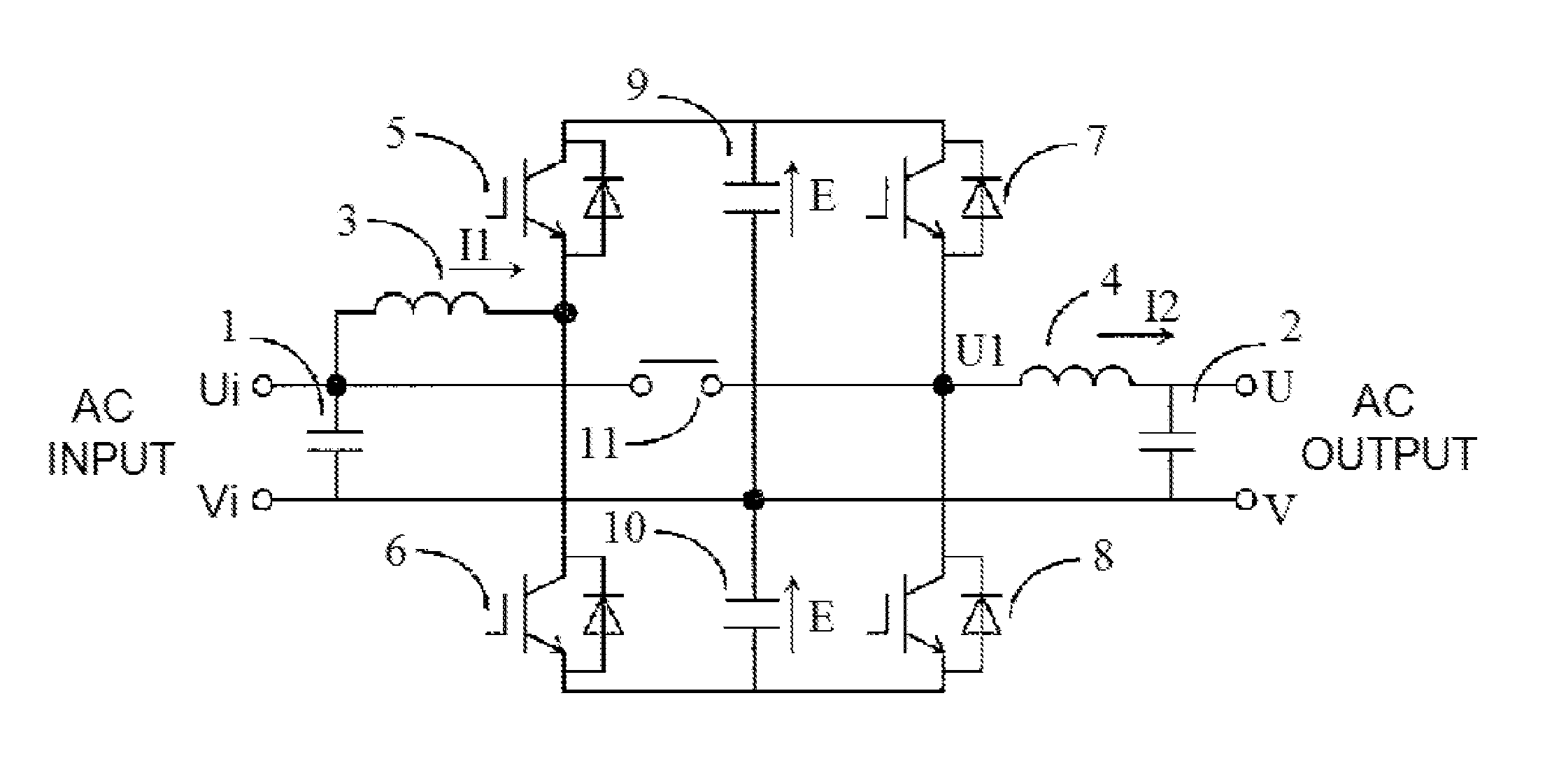
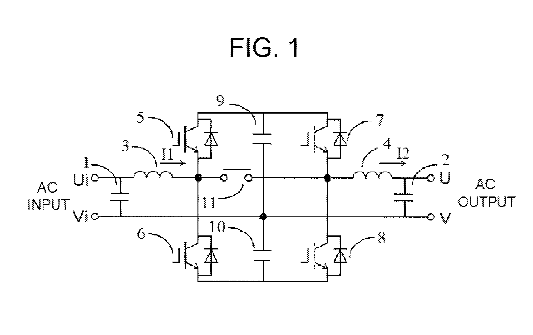
[0037]An AC-DC conversion / DC-AC conversion circuit configured of semiconductors in FIG. 4 is configured by a first IGBT series circuit wherein IGBTs 5 and 6, to each of which a diode is connected in anti-parallel, are connected in series, a second IGBT series circuit wherein IGBTs 7 and 8, to each of which a diode is connected in anti-parallel, are connected in series, and a capacitor series circuit wherein capacitors 9 and 10 are connected in series being connected in parallel.

[0038]A inductor 3 is connected between one end Ui of an alternating current input and a series connection point inside the first IGBT series circuit, a bidirectional switch 11 is connected between the one end Ui of the alternating current input and a series connection point inside the second IGBT series circuit, and a inductor...

example 2

[0054]FIG. 8 is a circuit diagram showing a second working example of the invention. Portions the same as in FIG. 4 are given the same reference signs, and a description thereof is omitted.

[0055]Working Example 2, having an object of reducing switching loss in the step-down mode, is such that a bidirectional semiconductor switch 12 is added between U1 and V. An operating principle thereof is shown in FIG. 9. In the step-down mode, the bidirectional switches 11 and 12 are turned on and off alternately. This configuration is an alternating current chopper circuit wherein the voltage between U1 and V becomes equivalent to the input voltage when the bidirectional switch 11 is turned on, and 0V when the bidirectional switch 12 is turned on. For example, when taking the ratio when the bidirectional switch 11 is turned on to be a constant value of 0.9, regardless of phase, the output voltage becomes 0.9 times the input voltage. This circuit is such that the voltage change range is equivale...

example 3

[0058]FIG. 10, being a circuit diagram showing a third working example of the invention, shows an example of application to a three-phase circuit. This three-phase circuit is an example wherein the circuit of the first working example illustrated in FIG. 4 is configured using three circuits. The series connection point inside the capacitor series circuit of the circuit of FIG. 4 is taken as a neutral point potential of the three-phase circuit, and shared by the three circuits. The switching circuit is such that both a forward conversion circuit portion and reverse conversion circuit portion are connected in parallel to a capacitor series circuit (45 and 46) for each of the three circuits. The forward conversion circuit portion is such that a series circuit of IGBTs 33 and 39, a series circuit of IGBTs 34 and 40, and a series circuit of IGBTs 35 and 41 are connected in parallel to the series circuit of the capacitors 45 and 46. The reverse conversion circuit portion is such that a se...


PUM


Abstract

An AC-AC converter configured of a forward converter that converts alternating current to direct current and a reverse converter that converts direct current to alternating current, wherein a first semiconductor switch series circuit, a second semiconductor switch series circuit, and a capacitor series circuit are connected in parallel, a first inductor is connected between one end of an alternating current input and a series connection point of the first semiconductor switch series circuit, a bidirectional switch is connected between the one end of the alternating current input and a series connection point of the second semiconductor switch series circuit, a second inductor is connected between the series connection point of the second semiconductor switch series circuit and one end of an alternating current output, and a series connection point of the capacitor series circuit is connected to the other end of the alternating current input and the other end of the alternating current output. Because of this, it is possible to keep the inductor loss of the rectifier sufficiently small when input voltage is within a specified range. Also, in addition to this, it is possible to reduce switching loss more than in heretofore known circuits when carrying out a compensation action.

Description

TECHNICAL FIELD[0001]The present invention relates to improving the efficiency of an uninterruptible power system that compensates for fluctuation of an alternating current voltage or for a power interruption, thus supplying a stable voltage to a load.BACKGROUND ART[0002]FIG. 1 is a diagram showing an example of a circuit configuration of an AC-AC converter described in PLT 1 shown below. In FIGS. 1, 1 and 2 are filter capacitors, 3 and 4 are inductors, 5 to 8 are IGBTs (Insulated Gate Bipolar Transistors) (semiconductor switches that can control the turning on and off of a forward current, and that are always in a state of conduction with respect to reverse current), and 9 and 10 are smoothing capacitors. A circuit configuration wherein the inductor 3 is connected between a series connection point of the IGBTs 5 and 6 of a parallel connection circuit of a series connection circuit of the IGBTs 5 and 6 and a series connection circuit of the capacitors 9 and 10 and one end of an alte...

Claims


Application Information

Patent Timeline
Patent Type & Authority Applications(United States)
IPC IPC(8): H02M5/458
CPCH02M5/4585H02M2001/0048H02J2009/063H02J9/06H02M1/0048Y02B70/10H02J9/063
Inventor YAMADA, RYUJI
Owner FUJI ELECTRIC CO LTD
Why Eureka
Try Eureka