Beam monitor system and particle beam irradiation system
a monitor system and beam technology, applied in the field of beam monitor system and particle beam irradiation system, can solve the problems of large scale of bean monitoring system alone, long time it takes to detect the position of charged particle beam, and large beam width, and achieve the effect of simple configuration
- Summary
- Abstract
- Description
- Claims
- Application Information
AI Technical Summary
Benefits of technology
Problems solved by technology
Method used
Image
Examples
first embodiment
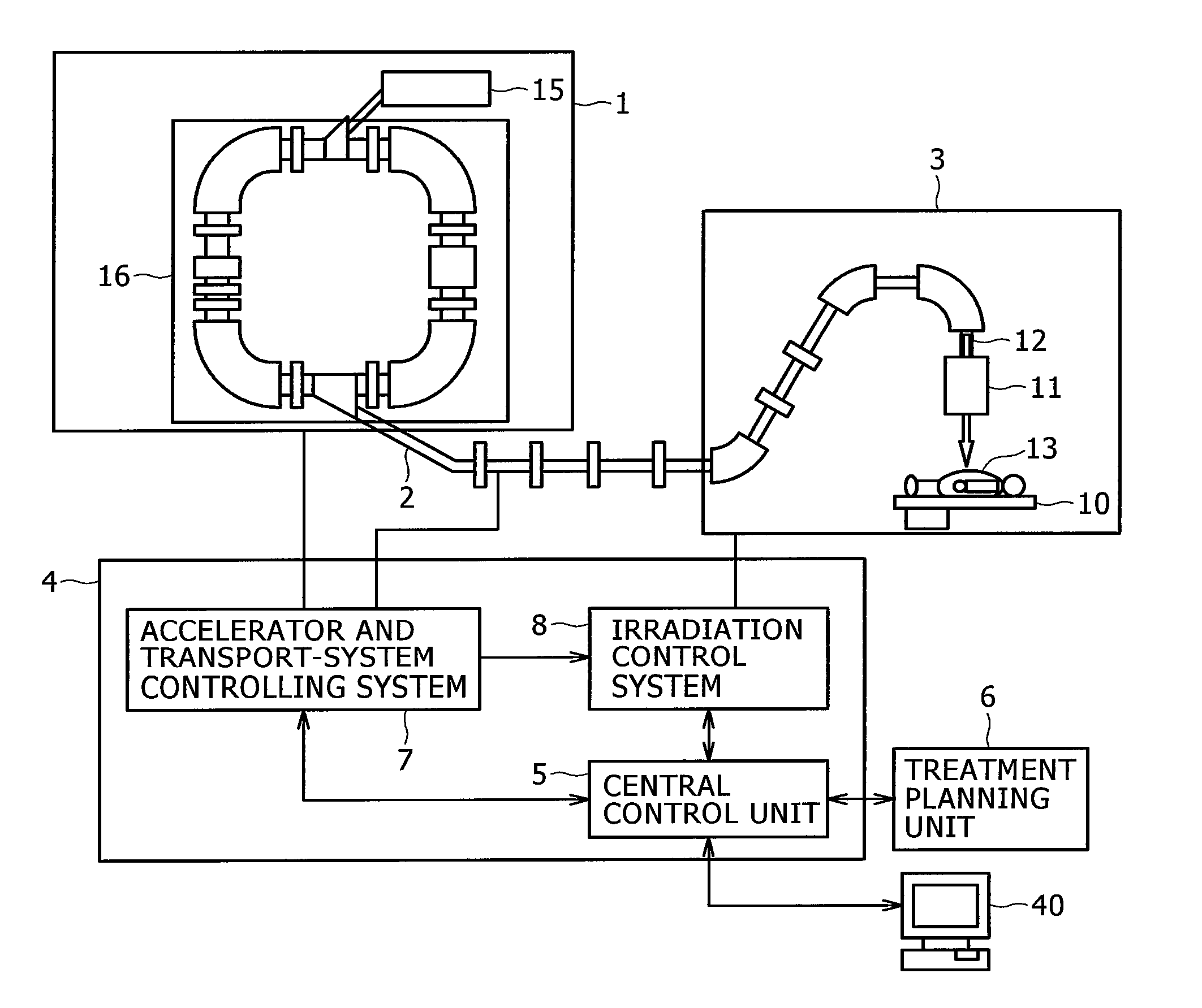
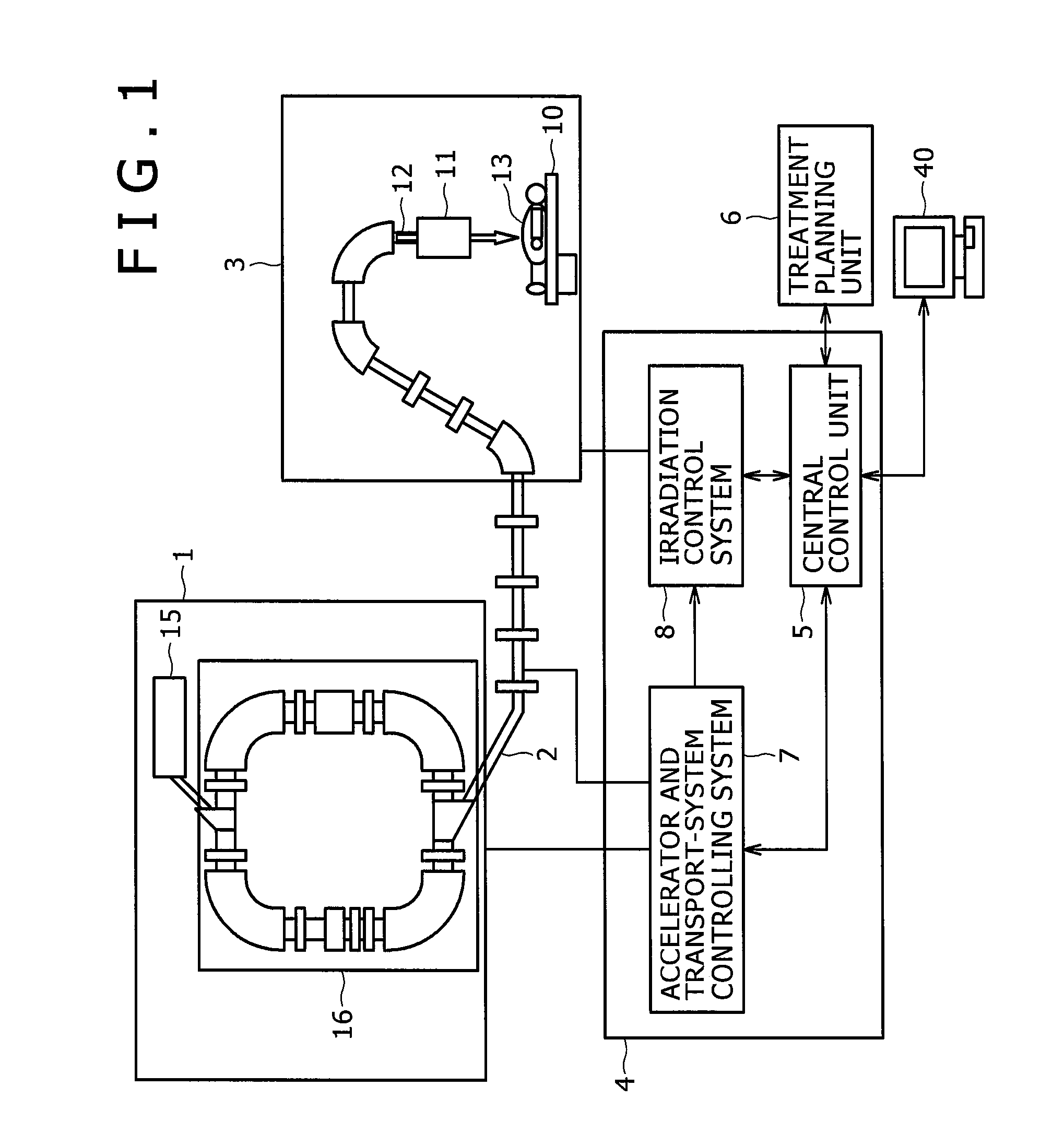
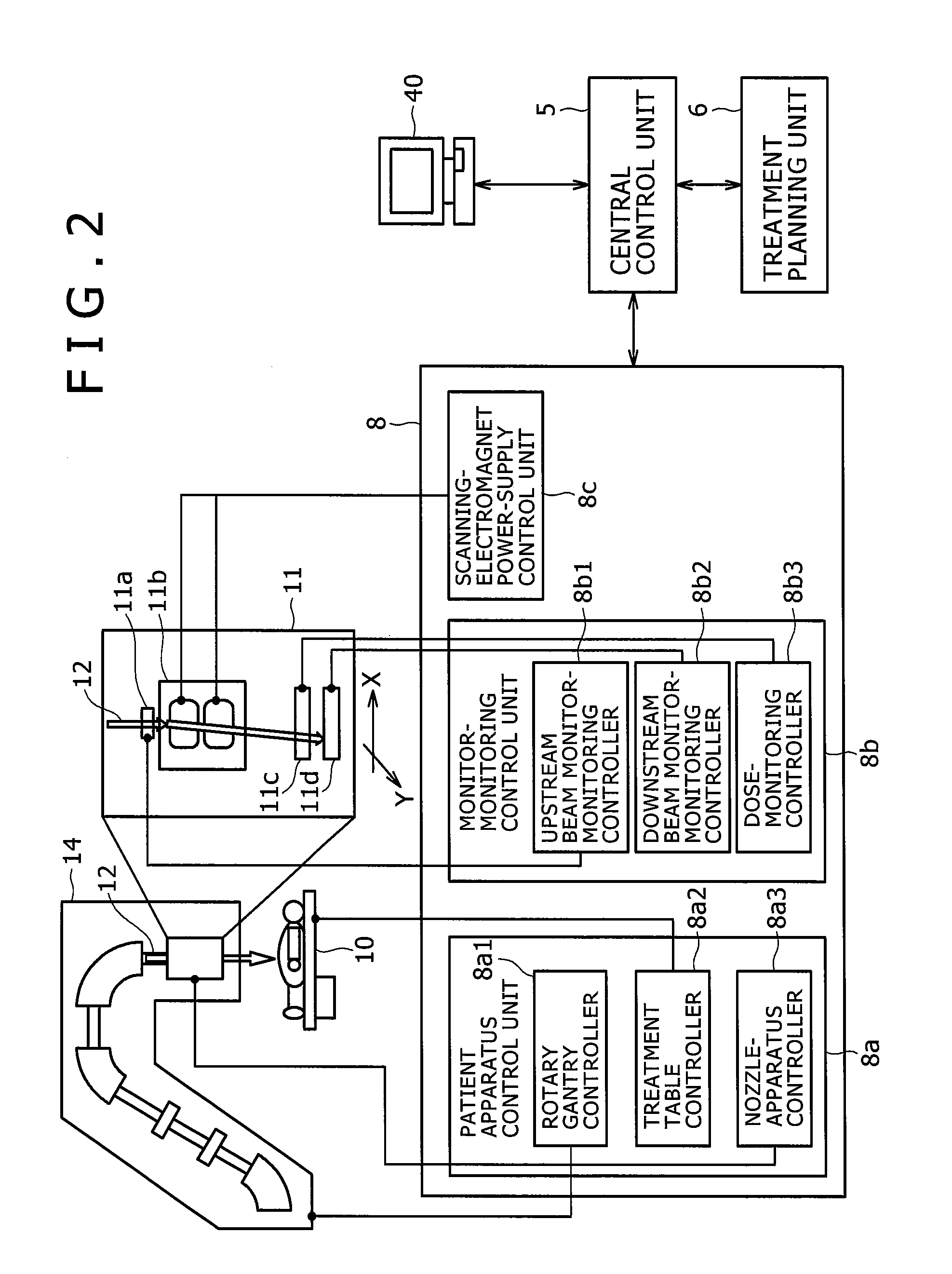
[0023]A preferred embodiment of a particle beam irradiation system according to the invention is described hereinafter with reference to FIGS. 1 and 2. The particle beam irradiation system is a system for irradiating an affected part of a patient fixed on a treatment table (a bed) 10 inside a treatment room with a charged particle beam 12 (for example, a proton beam, a carbon beam, and so forth).
[0024]The particle beam irradiation system according to the present embodiment is provided with a charged particle beam generation unit 1, a beam transport system 2, a scanning irradiation unit 3, and a control system 4. The beam transport system 2 connects the charged particle beam generation unit 1 to the scanning irradiation unit 3. The control system 4 is connected to a treatment planning unit 6, and an operation terminal 40, respectively. The operation terminal 40 is provided with an input device where an operator (a treatment worker) inputs data, and an instruction signal, and a displa...
second embodiment
[0060]There is described hereinafter a particle beam irradiation system according to another embodiment of the invention with reference to FIG. 8. With the particle beam irradiation system according to the first embodiment, the beam monitor system has the configuration whereby the two segments are organized into the one group, however, the particle beam irradiation system according to a second embodiment includes a beam monitor system whereby a plurality of segments are organized into one group. There is described hereinafter a configuration of the beam monitor system according to the present embodiment, differing from the case of the first embodiment.
[0061]The beam monitor system according to the present embodiment represents the case of a beam monitor system where group numbers are N-groups, and the number of the channels in the segment is Lch. Assuming that a beam distribution necessary for calculation of a beam position, and a beam width is to appear in (M−1) segment, the number...
third embodiment
[0066]There is described hereinafter a particle beam irradiation system according to a third embodiment of the invention with reference to FIG. 9. In contrast to the first embodiment relating to the particle beam irradiation system provided with the beam monitor system for monitoring the beam position, and the beam width in execution of the spot-scanning irradiation method, the particle beam irradiation system according to the present embodiment is provided with a beam monitor system for monitoring a beam position, and a beam width in execution of a raster scanning irradiation method. The particle beam irradiation system according to the present embodiment is provided with the beam monitor system for monitoring the beam position, and the beam width in execution of the raster scanning irradiation method whereby an affected part of a patient 13 is divided into a plurality of layers in the travelling direction of the charged particle beam, thereby scanning with the charged particle bea...
PUM
 Abstract
Description
Claims
Application Information
 - R&D
- Intellectual Property
- Life Sciences
- Materials
- Tech Scout
- Unparalleled Data Quality
- Higher Quality Content
- 60% Fewer Hallucinations
Browse by: Latest US Patents, China's latest patents, Technical Efficacy Thesaurus, Application Domain, Technology Topic, Popular Technical Reports.
© 2025 PatSnap. All rights reserved.Legal|Privacy policy|Modern Slavery Act Transparency Statement|Sitemap|About US| Contact US: help@patsnap.com


