Multiple Petal Deployable Telescope

a telescope and multi-petal technology, applied in the field of compact optical system, can solve the problems of limited imaging resolution, small satellites that are not suitable for small satellites, and most precision optical instruments limited by basic physics, so as to achieve higher signal level and resolution

Active Publication Date: 2013-09-05
UTAH STATE UNIVERSITY
View PDF6 Cites 20 Cited by
  • Summary
  • Abstract
  • Description
  • Claims
  • Application Information

AI Technical Summary

Problems solved by technology

However, small satellites fall short in optical performance due to their relatively small aperture size.
Even the most precision optical instruments are limited by basic physics.
With small aperture optical sensors in space, diffraction often limits the imaging resolution.
Grainy images and insufficient contrast, caused by a lack of signal or too much noise, are common manifestations of the lack of signal to noise ratio.

Method used


Image

  • Multiple Petal Deployable Telescope
  • Multiple Petal Deployable Telescope
  • Multiple Petal Deployable Telescope

Examples


Embodiment Construction

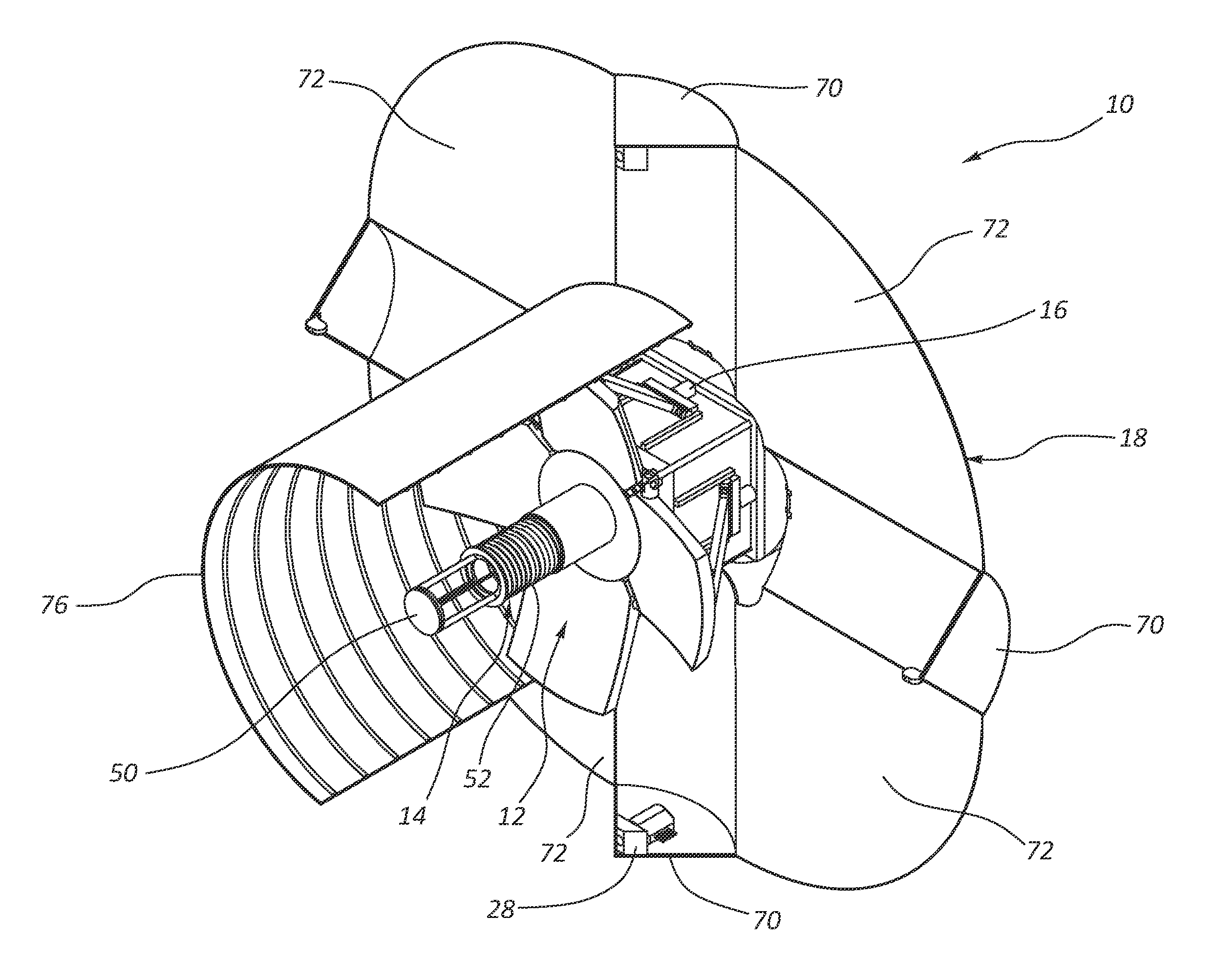
[0035]The present disclosure is directed to deployable telescopes, and more specifically related to opto-mechanical deployable telescopes. One aspect of the present disclosure relates to deployment and alignment systems for a multiple petal primary mirror of the telescope. The alignment system may use a kinematic or semi-kinematic (also referred to as “quasi-kinematic”) constraint system to align the petals relative to each other when the primary mirror is in a deployed position. The primary mirror may have a passive alignment and deployment system that uses stored mechanical energy to deploy the petals and orient the petals relative to each other. The stored mechanical energy may concurrently deploy the petals and align the petals relative to each other. The alignment system for the primary mirror may include a plurality of precision machined interfaces that define the kinematic or semi-kinematic constraints that provide positioning of the petals of the primary mirror in a deployed...


PUM


Abstract

An opto-mechanical deployable telescope includes a hub, at least one deployable multiple petal primary mirror mounted to the hub, a deployment assembly, and a deployment engine assembly. The deployment assembly is operable to move the at least one primary mirror between a stowed position and a deployed position. The deployment engine assembly is operable to power the deployment assembly using stored mechanical energy. The deployment assembly includes a kinematic or semi-kinematic interface between the hub and the at least one primary mirror to hold petals of the at least one primary mirror in alignment relative to each other in the deployed position.

Description

CROSS-REFERENCE TO RELATED APPLICATIONS[0001]This application claims priority to U.S. Provisional Patent Application No. 61 / 446,617, filed Feb. 25, 2011, and entitled MULTIPLE PETAL DEPLOYABLE TELESCOPE, the disclosure of which is incorporated by reference herein, in its entirety.TECHNICAL FIELD[0002]The present application relates generally to constrained volume optical systems, and more particularly relates to small package opto-mechanical telescope designs that provide relatively high signal levels and resolutions.BACKGROUND[0003]Small satellites offer promise for increased instrument presence in space as well as for tactical quick turn missions. However, small satellites fall short in optical performance due to their relatively small aperture size. Even the most precision optical instruments are limited by basic physics. With small aperture optical sensors in space, diffraction often limits the imaging resolution. For a circular aperture, this diffraction blur angle may be estim...

Claims


Application Information

Patent Timeline
Patent Type & Authority Applications(United States)
IPC IPC(8): G02B23/02
CPCG02B23/02H04B10/118B64G1/66G02B23/2476B64G1/222G02B23/20G02B7/183
Inventor NEWSWANDER, TRENTCROWTHER, BLAKECHAMPAGNE, JAMESNORRIS, ADAM
Owner UTAH STATE UNIVERSITY
Why Eureka
Try Eureka